Eureka AIR delivers breakthrough ideas for toughest innovation challenges, trusted by R&D personnel around the world.

Clock control circuit

A clock control and circuit technology, applied in the field of circuits, can solve problems affecting system performance and poor clock quality

Pending Publication Date: 2021-07-13
浙江赛思电子科技有限公司
View PDF5 Cites 2 Cited by
  • Summary
  • Abstract
  • Description
  • Claims
  • Application Information

AI Technical Summary

Problems solved by technology

[0002] At present, the clock control circuit with a single PLL (Phase Locked Loop) structure is susceptible to interference from IC chips, switching power supply noise, data or clock lines, resulting in random clock jitter and periodic clock jitter, making the overall clock quality poor and affecting system performance.

Method used


Image

  • Clock control circuit

Examples


Embodiment Construction

[0021] The following description serves to disclose the present invention to enable those skilled in the art to carry out the present invention. The preferred embodiments described below are only examples, and those skilled in the art can devise other obvious variations. The basic principles of the present invention defined in the following description can be applied to other embodiments, variations, improvements, equivalents and other technical solutions without departing from the spirit and scope of the present invention.

[0022] Those skilled in the art should understand that in the disclosure of the present invention, the terms "vertical", "transverse", "upper", "lower", "front", "rear", "left", "right", " The orientation or positional relationship indicated by "vertical", "horizontal", "top", "bottom", "inner", "outer", etc. is based on the orientation or positional relationship shown in the drawings, which are only for the convenience of describing the present invention...


PUM


Abstract

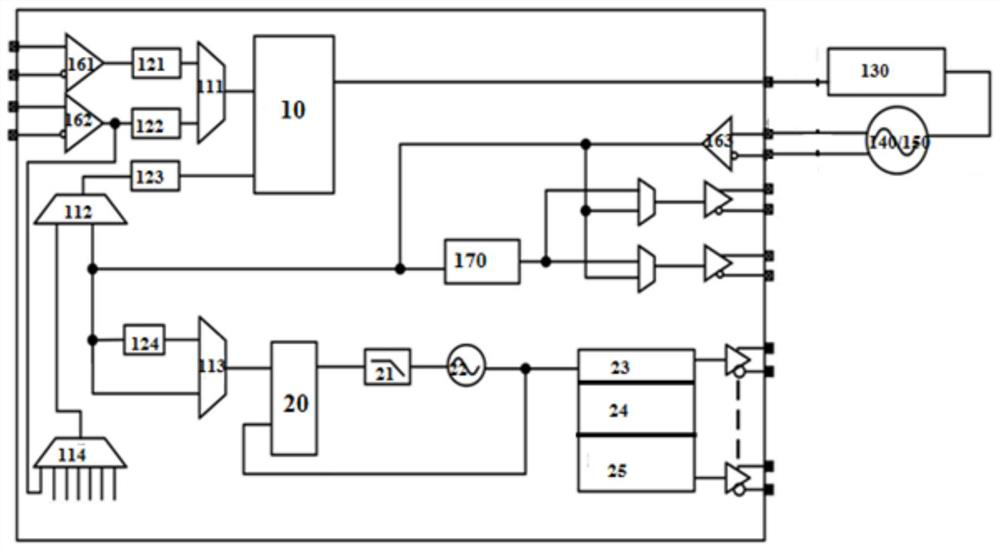
The invention discloses a clock control circuit, which comprises a first phase-locked loop, a second phase-locked loop and a third phase-locked loop, wherein the input end of the first phase-locked loop is connected with a first multiplexer; one end of the first phase-locked loop is connected with the output end of the second phase-locked loop, and an output signal of the first phase-locked loop is used as a reference signal of the second phase-locked loop; and the output end of the second phase-locked loop is connected with the phase shifter and the clock frequency divider and is used for controlling phase output after frequency division of the clock. A first PLL (Phase Locked Loop) in the clock control circuit is connected with a loop filter and a voltage-controlled crystal oscillator to form a PLL loop, so that a stable filtering clock can be output on the first PLL loop, and the stably output filtering clock is input into a second PLL loop to obtain an accurate jitter clock.

Description

technical field [0001] The invention relates to the field of circuits, in particular to a clock control circuit. Background technique [0002] At present, the clock control circuit with a single PLL (Phase Locked Loop) structure is susceptible to random clock jitter and periodic clock jitter due to interference from IC chips, switching power supply noise, data or clock lines, making the overall clock quality poor and affecting system performance. Contents of the invention [0003] One object of the present invention is to provide a clock control circuit, the clock control circuit adopts a dual PLL structure, wherein the output signal of one PLL is used as the input signal of the other PLL, so that the clock jitter can be effectively controlled and the clock quality can be improved. [0004] Another object of the present invention is to provide a clock control circuit. The first PLL in the clock control circuit is connected with a loop filter and a voltage-controlled crysta...

Claims


Application Information

Patent Timeline
Patent Type & Authority Applications(China)
IPC IPC(8): H03L7/087H03L7/099
CPCH03L7/087H03L7/099
Inventor 许文高楷渊孔维铭申佳
Owner 浙江赛思电子科技有限公司
Why Eureka
Eureka Blog
Learn More