
Handheld mobile printing device positioning method based on computer vision

A computer vision and mobile printing technology, applied in computing, measuring devices, using optical devices, etc., can solve the problems of low positioning frequency, large amount of calculation, and many cameras, and achieve high positioning frequency, low camera cost, and camera number. less effect

Active Publication Date: 2021-07-13
XIDIAN UNIV
View PDF17 Cites 2 Cited by
  • Summary
  • Abstract
  • Description
  • Claims
  • Application Information

AI Technical Summary

Problems solved by technology

[0005] The purpose of the present invention is to address the deficiencies of the above-mentioned prior art, and propose a positioning method for handheld mobile printing devices based on computer vision, which solves the problems existing in the existing positioning technology. The positioning frequency is low due to the large amount of calculation, and the high cost is caused by the large number of cameras required

Method used


Image

  • Handheld mobile printing device positioning method based on computer vision
  • Handheld mobile printing device positioning method based on computer vision
  • Handheld mobile printing device positioning method based on computer vision

Examples


Embodiment Construction

[0034] The present invention will be further described below with reference to the accompanying drawings and embodiments.

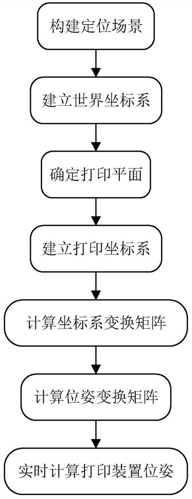
[0035] Refer to attached figure 1 , to further describe the specific implementation steps of the present invention.

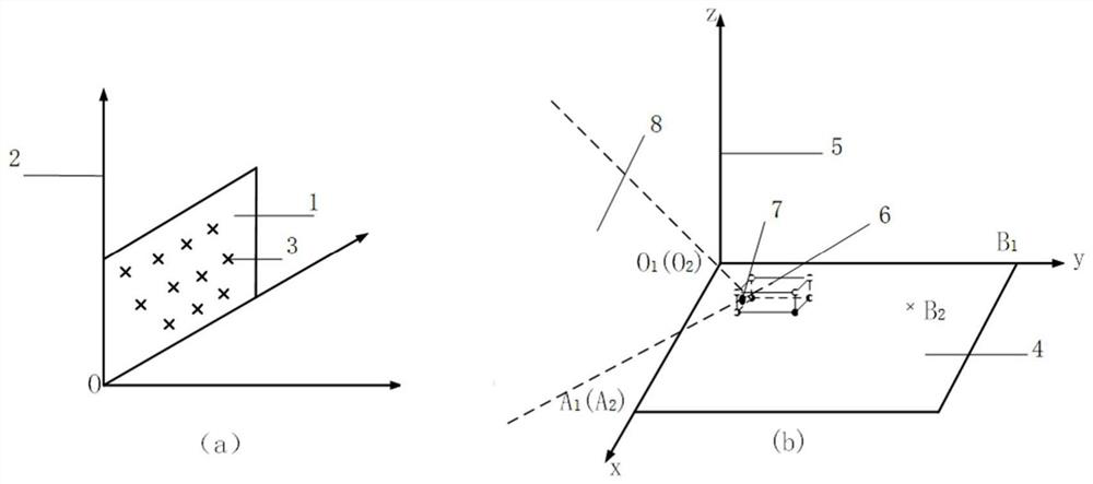
[0036] Step 1, build a positioning scene.

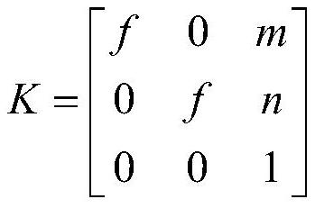
[0037] The marking pattern is placed in front of the camera on the handheld mobile printing device, so that the marking pattern is within the field of view of the camera. The marking pattern refers to any one of checkerboard, two-dimensional code, concentric rings, and grayscale patterns. The camera refers to a camera whose internal parameter matrix is ​​known and the captured images have been de-distorted. The internal parameter matrix is ​​as follows,

[0038]

[0039] Among them, K represents the internal parameter matrix of the camera, f represents the lens focal length value of the camera, m and n represent the offsets of the principal point of the camera on the x-axis and y-axis in th...


PUM


Abstract

The invention discloses a handheld mobile printing device positioning method based on computer vision. The handheld mobile printing device positioning method comprises the following steps: (1) constructing a positioning scene; (2) establishing a world coordinate system; (3) determining a printing plane; (4) establishing a printing coordinate system; (5) calculating a coordinate system transformation matrix; (6) calculating a pose transformation matrix; (7) calculating the pose of the printing device in real time. According to the invention, positioning is realized by using a single camera and a simple algorithm, and real-time positioning of the handheld mobile printing device is realized with relatively low cost.

Description

technical field [0001] The invention belongs to the field of space positioning, and further relates to a computer vision-based positioning method for a handheld mobile printing device in the field of space positioning. The invention is used in a hand-held mobile printing device. The camera on the printing device continuously acquires images, and the real-time positioning of the printing device itself can be realized by processing the images. Background technique [0002] Different from traditional printers, hand-held mobile printers are small in size, good in portability, and can print long strip patterns. Since there is no positioning function, if you want to print larger-format patterns, you can only rely on experience to manually splice and print. Often the splicing printing effect is not good. it is good. If the handheld mobile printer can obtain high-frequency and high-precision positioning information, then it can print the desired image according to the position of t...

Claims


Application Information

Patent Timeline
IPC IPC(8): G06T7/73G01B11/00
CPCG06T7/73G01B11/002G06T2207/30208
Inventor 姜光朱家辉陈浩
Owner XIDIAN UNIV
Learn More