
High-temperature and high-pressure conventional triaxial direct shear fracture seepage coupling testing device and use method

A high-temperature and high-pressure, testing device technology, applied in measuring devices, using stable shear force to test material strength, using stable tension/pressure to test material strength, etc. Shear rupture permeability test and other problems, to achieve the effect of simple structure and cost reduction

Active Publication Date: 2021-07-13
NORTHEASTERN UNIV
View PDF10 Cites 6 Cited by
  • Summary
  • Abstract
  • Description
  • Claims
  • Application Information

AI Technical Summary

Problems solved by technology

[0006] In view of the above-mentioned shortcomings and deficiencies of the prior art, the present invention provides a high-temperature and high-pressure conventional three-axis direct shear fracture-seepage coupling test device and its use method, which solves the problem that the existing rock sample shearing device cannot perform rock three-axis direct shear. The technical problem of the fracture permeability test and the inability to meet the temperature-seepage-stress (THM) multi-field coupling environment required for the rock triaxial direct shear fracture test

Method used


Image

  • High-temperature and high-pressure conventional triaxial direct shear fracture seepage coupling testing device and use method
  • High-temperature and high-pressure conventional triaxial direct shear fracture seepage coupling testing device and use method
  • High-temperature and high-pressure conventional triaxial direct shear fracture seepage coupling testing device and use method

Examples


Embodiment Construction

[0077] In order to better explain the present invention and facilitate understanding, the present invention will be described in detail below through specific embodiments in conjunction with the accompanying drawings. Among them, the directional nouns such as "up" and "down" mentioned in this article are based on figure 1 orientation as a reference.

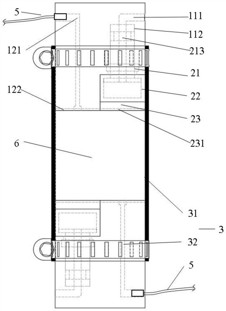
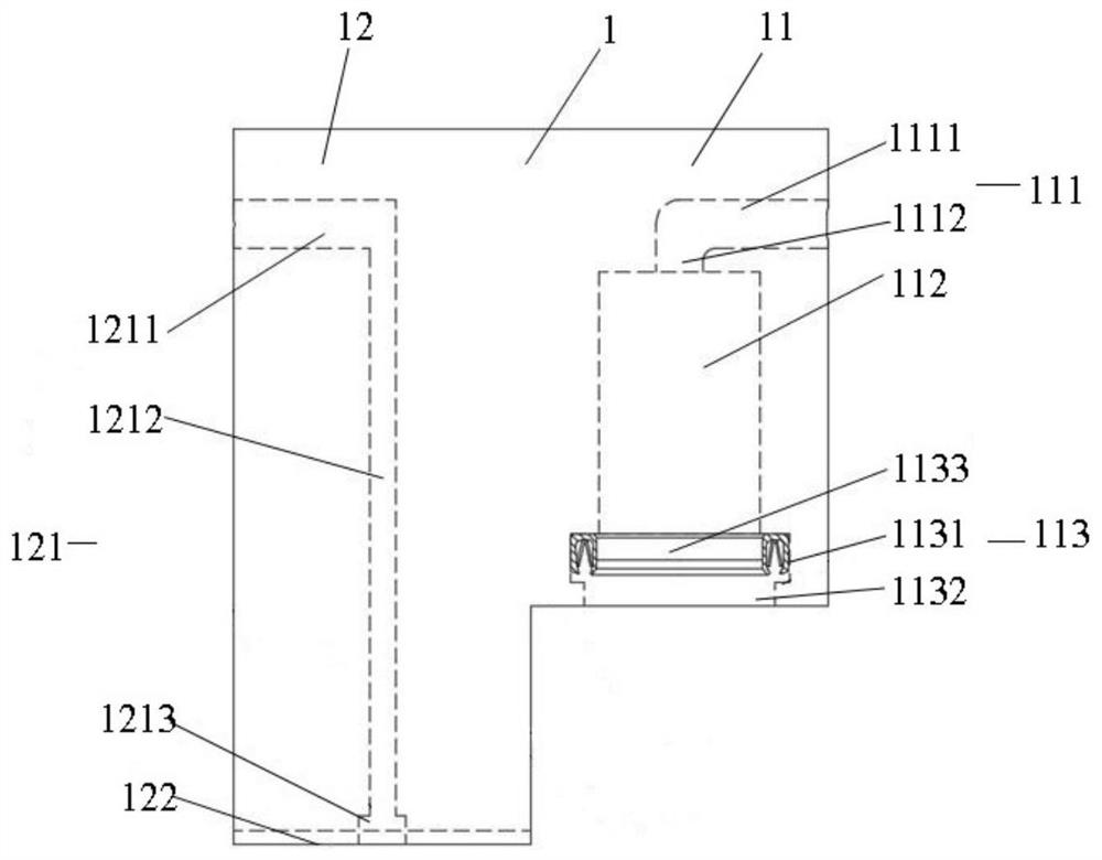
[0078] refer to figure 1 and figure 2 , the embodiment of the present invention proposes a high temperature and high pressure conventional three-axis direct shear fracture-seepage coupling test device, including two shear indenters 1, two pressure components 2, a fixing component 3 and a pipetting component 4.

[0079] The two shear indenters 1 and the two pressure assemblies 2 are respectively arranged on the upper and lower sides of the rock sample 6 in a symmetrical manner with respect to the center of the rock sample 6 . The fixed component 3 is sleeved on the rock sample 6, two shear pressure heads 1 and two pressure com...


PUM


Abstract

The invention relates to a high-temperature and high-pressure conventional triaxial direct shear fracture seepage coupling testing device. Two shear pressure heads and two pressure assemblies are arranged on the upper portion and the lower portion of a rock sample in a manner of being symmetrical about the center of the rock sample. The shear pressure head includes first and second shear pressure head bodies. The pressure assembly comprises a rubber bag and a base plate. A part of the pressure assembly is arranged in a space formed by the height difference of the first shearing pressure head and the second shearing pressure head. The rubber bag applies pressure to the rock sample through the base plate. Seepage media in a first seepage network groove formed in the second shearing pressure head body and a second seepage network groove formed in the base plate apply seepage pressure to the rock sample. The triaxial testing machine applies lateral confining pressure, axial pressure and high temperature to the rock sample. The testing device has the beneficial effects that the testing device can be used for carrying out a conventional triaxial direct shear fracture seepage test under high-temperature and high-pressure conditions. Through the simple structure, the optimized sealing design, the connection mode of the piston component and the rubber bag and the liquid injection method design, the practicability and reliability of the device are greatly improved.

Description

technical field [0001] The invention relates to the technical field of rock experiments, in particular to a high-temperature and high-pressure conventional three-axis direct shear fracture seepage coupling test device and a use method. Background technique [0002] With the in-depth development of resource mining and energy development in rock engineering, in order to facilitate the development of geothermal energy production, oil and gas production, deep well injection, carbon dioxide sequestration and nuclear waste treatment, it is necessary to predict and analyze the flow of seepage media through fracture networks. description, in order to better improve the technical capabilities of mining and development, and avoid the inaccurate prediction and description of seepage medium flowing through the fracture network during actual mining, which may cause earthquakes induced by seepage medium injection, CO 2 and the hazards of gas storage leaks. The basic occurrence environmen...

Claims


Application Information

Patent Timeline
Patent Type & Authority Applications(China)
IPC IPC(8): G01N3/24G01N3/02G01N3/18G01N15/08
CPCG01N3/24G01N3/18G01N3/02G01N15/0806G01N15/0826G01N2203/0019G01N2203/0025G01N2203/0048G01N2203/0226G01N2203/0232G01N2203/0256
Inventor 刘造保刘斌慧冉亚东郝良吴名徐建宇李航
Owner NORTHEASTERN UNIV
Learn More