A Method for Eliminating Water Hammer in Mine Drainage Pipeline
A technology for drainage pipelines and water hammer, applied in the direction of pipe components, pipes/pipe joints/pipe fittings, mechanical equipment, etc., can solve the problems affecting production and construction safety, general water hammer removal effect, disconnection of pipe joints, etc. The effect of eliminating water hammer, ensuring normal production and increasing stability
- Summary
- Abstract
- Description
- Claims
- Application Information
AI Technical Summary
Problems solved by technology
Method used
Image
Examples
Embodiment 1
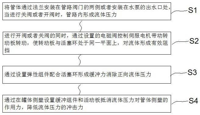
[0048] like Figure 7 As shown, a method for eliminating water hammer in a mine drainage pipeline includes the following steps:
[0049] S1: Install the pipe body on both sides of the pipeline valve or at the water outlet of the pump through the flange. When the valve is closed or opened, fluid pressure will be formed in the pipeline;
[0050] S2: At the same time of opening or closing the valve, the servo motor is controlled by the set solenoid valve to drive the rotating plate to rotate, so that the rotating plate and the piston ring are on the same plane, which effectively blocks the water flow;
[0051] S3: Eliminate the positive fluid pressure by setting the elastic component to cooperate with the piston ring to form a buffer force;
[0052] S4: By setting buffer components and movable plates on the side wall of the pipe body to counteract the force of the water hammer on the side wall of the pipe body, the impact force of the fluid pressure is reduced.
[0053] In step...
Embodiment 2
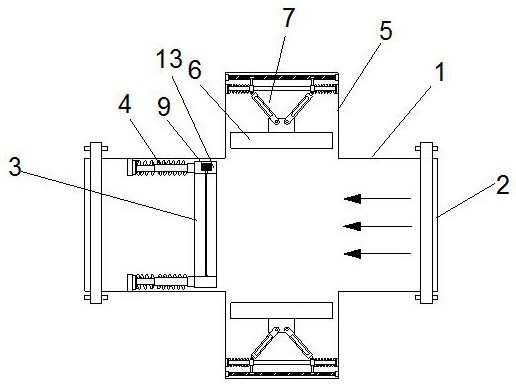
[0059] like figure 1 , 3 , 4, a method for eliminating water hammer of mine drainage pipeline; including a pipe body 1 and a flange 2; the end positions of the pipe body 1 are provided with flanges 2, and the pipe Body 1 is connected to the water pipe;
[0060] The upper and lower sides of the pipe body 1 are connected with a box body 5, and the side of the box body 5 close to the pipe body 1 is provided with a movable plate 6, and the movable plate 6 is connected with a buffer assembly 7. The component 7 is connected with the inner wall of the box body 5;
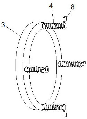
[0061] The inner wall of the pipe body 1 is provided with a piston ring 3, the center of the piston ring 3 is provided with a rotating plate 10, the rotating plate 10 can rotate inside the piston ring 3, and one side of the piston ring 3 is connected with a plurality of elastic components 4, The other ends of the plurality of elastic components 4 are connected with a connecting block 8 , and the other end of the connect...
Embodiment 3
[0063] like figure 2 , 5 As shown, on the basis of the first embodiment, a hollow cavity 13 is provided between the inner wall and the outer wall of the piston ring 3, the piston ring 3 and the inner wall of the pipe body 1 are sealed and slidingly connected by a rubber ring, and the cavity The inside of 13 is provided with a servo motor 9, the output shaft of the servo motor 9 penetrates the inner wall of the piston ring 3, and the output shaft of the servo motor 9 is connected with a rotating shaft 11, the rotating shaft 11 is connected with the rotating plate 10, and the rotating shaft 11 is arranged in the rotation. The center position of the plate 10 drives the rotating plate 10 to rotate; the rotating plate 10 has a circular structure, and when the rotating plate 10 and the piston ring 3 are closed, it is used to block water flow.
[0064] The elastic components 4 are evenly and symmetrically distributed on one side of the piston ring 3. The elastic components 4 includ...
PUM
 Abstract
Description
Claims
Application Information
 - R&D
- Intellectual Property
- Life Sciences
- Materials
- Tech Scout
- Unparalleled Data Quality
- Higher Quality Content
- 60% Fewer Hallucinations
Browse by: Latest US Patents, China's latest patents, Technical Efficacy Thesaurus, Application Domain, Technology Topic, Popular Technical Reports.
© 2025 PatSnap. All rights reserved.Legal|Privacy policy|Modern Slavery Act Transparency Statement|Sitemap|About US| Contact US: help@patsnap.com


