Rotary valve embedded half-bridge guide and control mechanism and fluid control valve

A fluid control valve, embedded technology, applied in the direction of fluid pressure actuation device, fluid pressure actuation system components, mechanical equipment, etc., can solve the problems of complex structure, large volume, low commutation frequency, etc., to achieve the overall volume Small, simple and ingenious structure, the effect of simplified structure

Active Publication Date: 2021-07-13
WENZHOU UNIVERSITY
View PDF6 Cites 0 Cited by
  • Summary
  • Abstract
  • Description
  • Claims
  • Application Information

AI Technical Summary

Problems solved by technology

[0007] The purpose of the present invention is to provide a rotary valve built-in half-bridge pilot control mechanism and a fluid control valve to solve the problems of the existing medium and large flow fluid control valves, which are large in size, complex in structure and low in frequency of reversing

Method used


Image

  • Rotary valve embedded half-bridge guide and control mechanism and fluid control valve
  • Rotary valve embedded half-bridge guide and control mechanism and fluid control valve
  • Rotary valve embedded half-bridge guide and control mechanism and fluid control valve

Examples


Embodiment 1

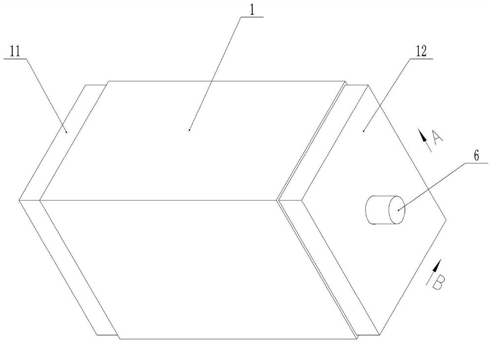
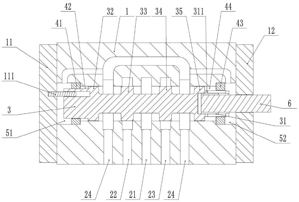
[0049] Example figure 1 As shown, the rotary valve embedded half-bridge pilot control mechanism and the fluid control valve include the valve body 1, the main valve core 3 and the pilot valve core 6, the main valve core 3 is slidably connected inside the valve body 1, and the pilot valve core 6 rotates Connected to the right end of the main spool 3, the left end of the valve body 1 is the left end cover 11, and the left end cover 11, the valve body 1 and the left end of the main spool 3 form a left adjustment cavity 51; the left end cover 11 is fixedly connected with a positioning pin 111 for positioning The pin 111 is arranged eccentrically with the main valve core 3, and the left end of the main valve core 3 is provided with a slide hole, and the positioning pin 111 is slidably connected with the left end of the main valve core 3 through the slide hole. The right end of the valve body 1 is the right end cover 12, the right end cover 12, the right end of the valve body 1 and ...

Embodiment 2

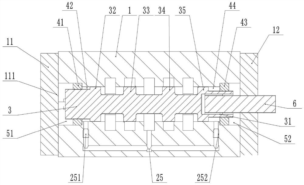
[0059] The difference between this embodiment and Embodiment 1 is that 12 oil grooves 61 are provided in this embodiment, and the 12 oil grooves 61 are evenly distributed along the circumferential direction of the pilot valve core 6, and there are 12 corresponding inner oil ports 311. The 12 inner oil ports 311 are evenly distributed along the circumferential direction of the main valve core 3, the positions of the 12 inner oil ports 311 can correspond to the positions of the 12 oil grooves 61, and the increase in the number of inner oil ports 311 can increase the flow area. When the control valve is in use, every time the pilot spool 6 rotates one revolution, the pilot stage valve port will switch 12 times to realize further amplification of the switching frequency.


PUM


Abstract

The invention belongs to the technical field of fluid transmission and control, and discloses a rotary valve embedded half-bridge guide and control mechanism and a fluid control valve. The rotary valve embedded half-bridge guide and control mechanism comprises a valve body and a main valve element, and the valve body is provided with a high-pressure oil inlet, a first control oil port, a second control oil port and a low-pressure oil outlet. A pilot valve element is further included. A left pilot cavity is defined by the left portion of the main valve element and the valve body, a right pilot cavity is defined by the right portion of the main valve element and the valve body, and the driving area of the left pilot cavity is smaller than that of the right pilot cavity. The pilot valve element is in sealed rotating connection with the main valve element, a plurality of oil grooves are formed in the pilot valve element, an inner oil port is formed in the main valve element, and the oil grooves and the right pilot cavity can be communicated through the inner oil port when the pilot valve element rotates. And oil holes for communicating the left pilot cavity with the high-pressure oil inlet and communicating the right pilot cavity with the high-pressure oil inlet are formed in the valve body. Compared with the prior art, through the simple and ingenious structure of the control valve, the fluid control valve with medium and large flow is made available, the overall size is small, the structure is simple, and the reversing frequency is greatly increased.

Description

technical field [0001] The invention belongs to the technical field of fluid control transmission and control, and specifically discloses a rotary valve embedded half-bridge guiding mechanism and a fluid control valve. Background technique [0002] The hydraulic reversing valve in the fluid control valve is used to control the flow, pressure and switch the oil circuit. For example, the electromagnetic reversing valve plays the role of controlling the flow and switching the oil circuit. At present, the hydraulic electromagnetic reversing valves on the market are divided into: 6 diameters, 10 diameters, 16 diameters and above (25, 32, etc.) hydraulic electromagnetic reversing valves. [0003] Fluid control valves used for small flows are generally in the form of single-stage direct-acting valves, that is, 6-diameter and 10-diameter hydraulic electromagnetic reversing valves are generally direct-acting valves (the electromagnetic force generated by the electromagnet directly p...

Claims


Application Information

Patent Timeline
Patent Type & Authority Applications(China)
IPC IPC(8): F15B13/02F15B21/00
CPCF15B13/02F15B21/00
Inventor 任燕汤何胜李勇周余庆钟永腾向家伟
Owner WENZHOU UNIVERSITY
Why Eureka
Try Eureka