A multi-clamp clamp
A multi-clamp and fixture technology, which is applied in the mechanical field, can solve the problems of affecting the processing quality of workpieces, lack of two-handed auxiliary fixation, and poor consistency of workpieces, etc., to achieve high fixing accuracy and consistency, good consistency, and consistent consistency. Effect
- Summary
- Abstract
- Description
- Claims
- Application Information
AI Technical Summary
Problems solved by technology
Method used
Image
Examples
Embodiment 1
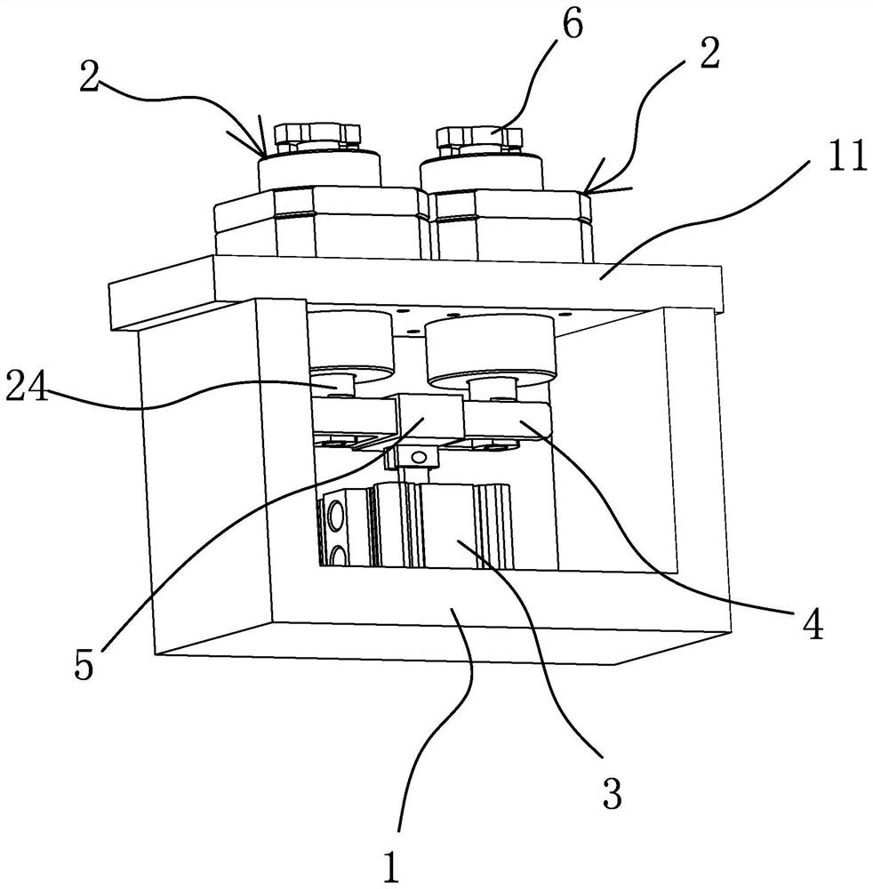
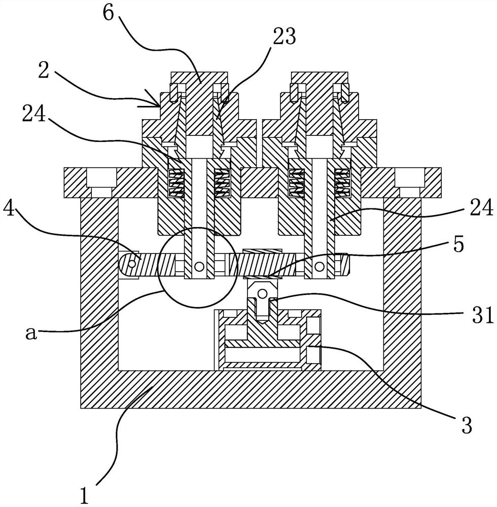
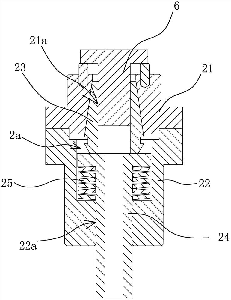
[0026] like figure 1 , figure 2 As shown, a multi-clamp clamp includes a base body 1, a power source 3 and several clamping mechanisms 2, wherein the base body 1 is roughly in the shape of a square box, and the clamping mechanism 2 is arranged on the top plate 11 of the base body 1 , the power source 3 is arranged at the bottom of the inner cavity of the seat body 1. In this embodiment, there are two clamping mechanisms 2. The power source 3 can be a device that can provide linear power such as an air cylinder or a hydraulic cylinder. A pendulum rod 4 is hinged on the side wall, and the pendulum rod 4 is arranged approximately horizontally and is located between the power source 3 and each clamping mechanism 2. The clamping mechanisms 2 are arranged at intervals along the length direction of the pendulum rod 4, and each clamping mechanism In the mechanism 2, the driving rod 24 used to control the clamping and loosening of the chuck 23 is connected with the swing rod 4, and t...
Embodiment 2
[0033] like Figure 5 As shown, the technical solution of this embodiment is basically the same as that of the first embodiment, the difference is that in this embodiment, the driving rod 24 of the clamping mechanism 2 and the chuck 23 are not directly connected, and the driving rod 24 is not directly connected. A guide hole three 241 is opened in the axial direction, and one end of the chuck 23 facing the driving rod 24 has a guide rod 231 extending along its axial direction. One end of the third 241 protrudes out of the guide hole 3 241 and is provided with a limiting shoulder 28 that can abut against the end face of the driving rod 24 . There is a certain distance between the end face of the collet 23 and the driving rod 24 and an elastic member 27 is provided. The end face of the collet 23 provided with the guide rod 231 has an annular boss 232 arranged around the guide rod 231. The length of the elastic member Greater than the height of the annular boss 232 , one end of ...
PUM
 Abstract
Description
Claims
Application Information
 - Generate Ideas
- Intellectual Property
- Life Sciences
- Materials
- Tech Scout
- Unparalleled Data Quality
- Higher Quality Content
- 60% Fewer Hallucinations
Browse by: Latest US Patents, China's latest patents, Technical Efficacy Thesaurus, Application Domain, Technology Topic, Popular Technical Reports.
© 2025 PatSnap. All rights reserved.Legal|Privacy policy|Modern Slavery Act Transparency Statement|Sitemap|About US| Contact US: help@patsnap.com


