
Auxiliary welding device for valve seat and bottle cap in fire extinguisher bottle body

A technology for auxiliary devices and fire extinguishers, applied in auxiliary devices, welding/cutting auxiliary equipment, welding equipment, etc., can solve the problems of restricting the working efficiency of the welding process, hazards to the physical and mental health of workers, and dazzling light, so as to reduce manual participation and improve welding efficiency. Efficiency, well-structured effect

Inactive Publication Date: 2021-07-13
来安县誉强消防科技有限公司
View PDF0 Cites 2 Cited by
  • Summary
  • Abstract
  • Description
  • Claims
  • Application Information

AI Technical Summary

Problems solved by technology

Through the analysis, it is not difficult to find that the above-mentioned welding process seriously restricts the work efficiency of the welding process because the workers participate in the two processes of feeding and retrieving.
At the same time, the above-mentioned welding process will inevitably produce dazzling light and harmful smoke, which will cause serious harm to the physical and mental health of workers over time.

Method used


Image

  • Auxiliary welding device for valve seat and bottle cap in fire extinguisher bottle body
  • Auxiliary welding device for valve seat and bottle cap in fire extinguisher bottle body
  • Auxiliary welding device for valve seat and bottle cap in fire extinguisher bottle body

Examples


Embodiment Construction

[0029] In order to make the technical means, creative features, goals and effects achieved by the present invention easy to understand, the present invention will be further described below in conjunction with specific embodiments.

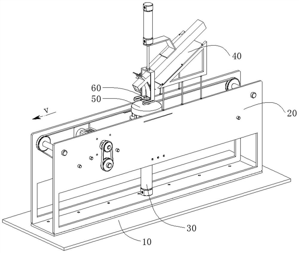
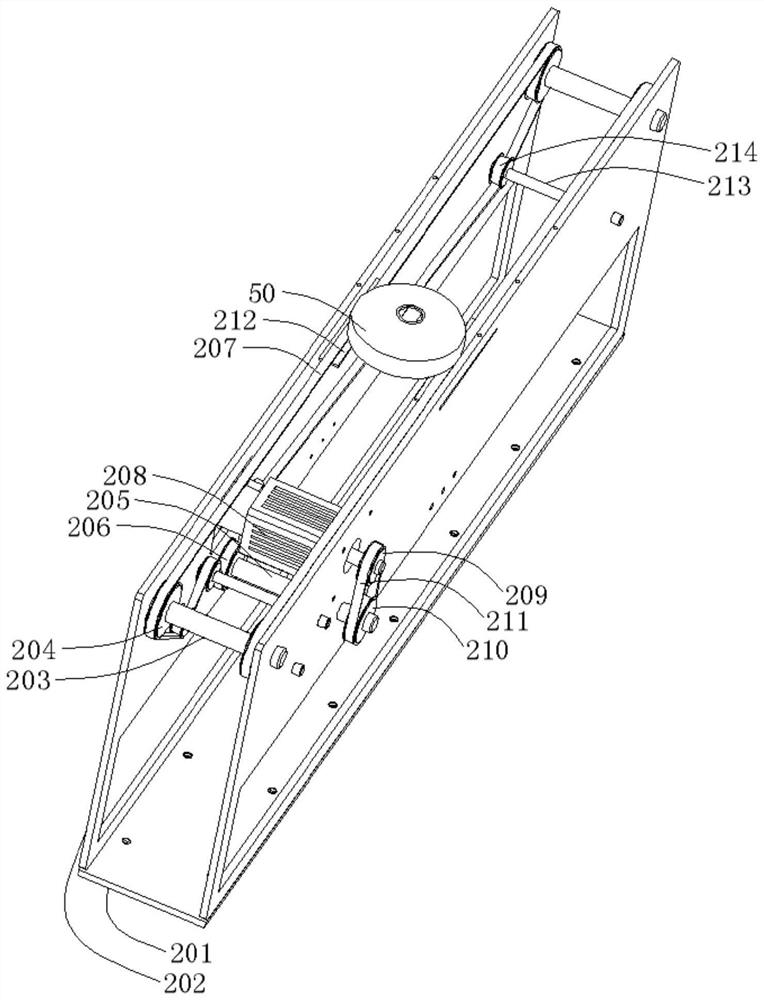
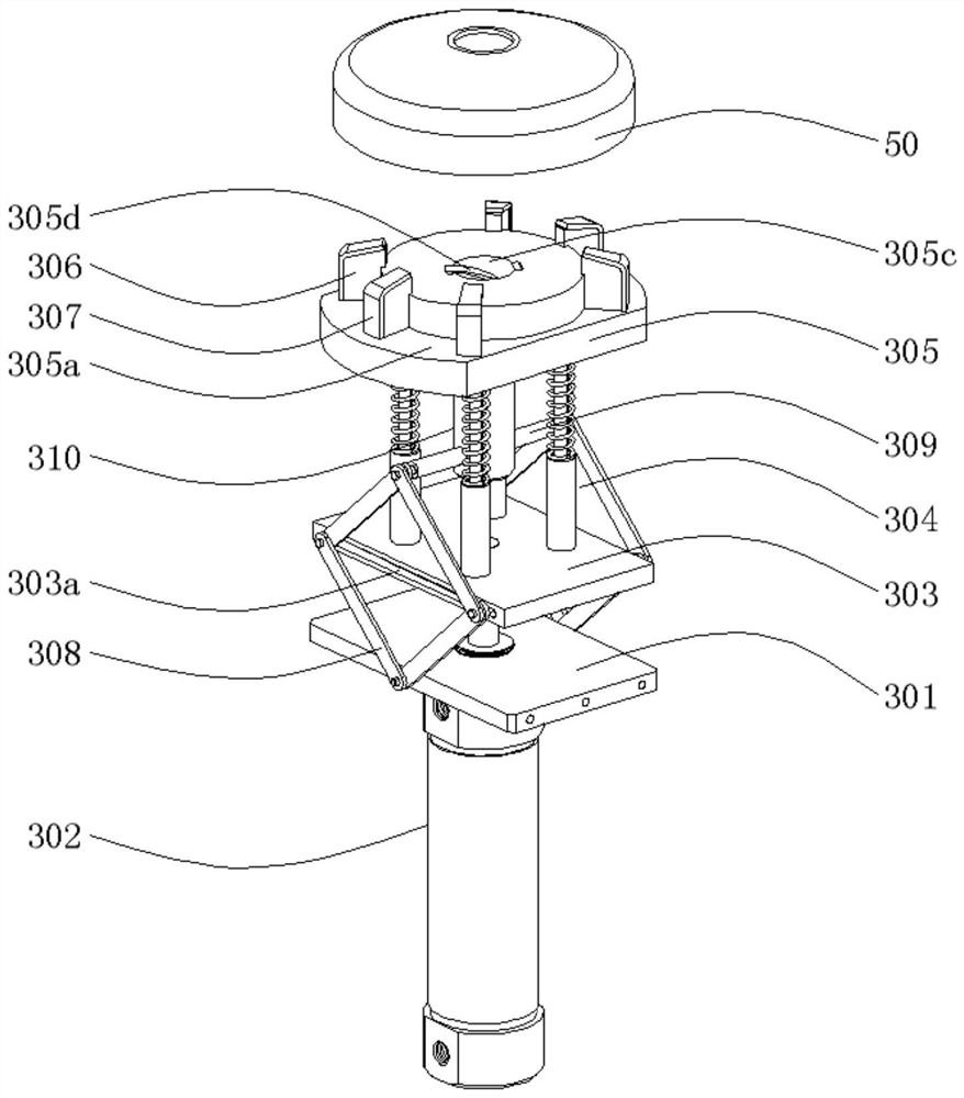
[0030] Such as Figure 1 to Figure 7 As shown, a welding auxiliary device for a valve seat and a bottle cap in a fire extinguisher bottle includes a working platform 10, a conveying mechanism 20, a jacking mechanism 30 and a lowering mechanism 40, wherein:

[0031] The working platform 10 is set horizontally;

[0032] The conveying mechanism 20 is arranged on the upper side of the working platform 10 and is used for intermittently conveying the bottle caps 50 which are not welded or have welded valve seats 60;

[0033] The jacking mechanism 30 is arranged on the inner side of the conveying mechanism 20 and is used for jacking up the bottle cap 50 so as to be pressed against and welded with the descending valve seat 60;

[0034] The lowering mech...


PUM


Abstract

The invention discloses an auxiliary welding device for a valve seat and a bottle cap in a fire extinguisher bottle body, and relates to the technical field of fire extinguisher production. The auxiliary welding device for the valve seat and the bottle cap in the fire extinguisher bottle body comprises a working platform, a conveying mechanism, a jacking mechanism and a lowering mechanism, wherein the conveying mechanism is arranged on the upper side of the working platform and intermittently conveys the bottle cap with the valve seat not welded or welded; the conveying device comprises a transverse plate I, a vertical plate I, a conveying shaft, a driving shaft, a conveying motor and a lifting strip; the jacking mechanism is arranged on the inner side of the conveying mechanism and used for jacking the bottle cap, so that the bottle cap can abut against and be welded to the descending valve seat conveniently; the jacking mechanism comprises a fixing plate I, a telescopic air cylinder I, a lifting plate, a positioning plate and a telescopic frame; the lowering mechanism is arranged above the jacking mechanism and used for lowering the valve seat, so that the valve seat can abut against and be welded to the rising bottle cap conveniently; and the lowering mechanism comprises a discharging pipe, a lifting plate, a material blocking strip, a material taking block, a fixing plate II and a telescopic air cylinder II. In conclusion, the auxiliary welding device for the valve seat and the bottle cap in the fire extinguisher bottle body provided by the invention is ingenious in design and reasonable in structure, manual participation is reduced, and the welding efficiency is improved.

Description

technical field [0001] The invention relates to the technical field of fire extinguisher production, in particular to a welding auxiliary device for a valve seat and a bottle cap in a fire extinguisher bottle body. Background technique [0002] At present, when manufacturing the bottle body of a fire extinguisher, it is necessary to weld the valve seat to the bottle mouth of the bottle cap in advance. Specifically, the valve seat is manually placed on the bottle mouth of the bottle cap, and then transferred to the rotatable positioning. On the positioning plate, an annular weld is formed between the valve seat and the bottle cap by an automatic welding machine, and finally the welded bottle cap is removed from the positioning plate manually. Through analysis, it is not difficult to find that the above-mentioned welding process seriously restricts the work efficiency of the welding process because workers participate in the two processes of feeding and retrieving. Simultaneo...

Claims


Application Information

Patent Timeline
IPC IPC(8): B23K37/00B23K31/02
CPCB23K31/02B23K37/00
Inventor 任斌李霞
Owner 来安县誉强消防科技有限公司
Learn More