
Deep hole boring machine with high machining precision

A technology of machining accuracy and boring machine, which is applied in metal processing equipment, metal processing mechanical parts, parts of boring machine/drilling machine, etc. It can solve the problems of low precision of deep holes, large differences in deep hole specifications, easy to produce eccentricity, etc., and saves money. Cost, easy adjustment and operation, the effect of prolonging the service life

Active Publication Date: 2021-07-13
浙江省平湖市北辰实业有限公司
View PDF8 Cites 0 Cited by
  • Summary
  • Abstract
  • Description
  • Claims
  • Application Information

AI Technical Summary

Problems solved by technology

[0004] Aiming at the deficiencies of the prior art, the present invention provides a deep hole boring machine with high processing precision, which solves the problem that the drill rods of the horizontal deep hole boring machine currently used are prone to eccentricity after long-term work, resulting in low precision of the processed deep holes , in severe cases, the processed deep hole will be quite different from the standard specification, which will affect the pass rate of the workpiece

Method used


Image

  • Deep hole boring machine with high machining precision
  • Deep hole boring machine with high machining precision
  • Deep hole boring machine with high machining precision

Examples


Embodiment 1

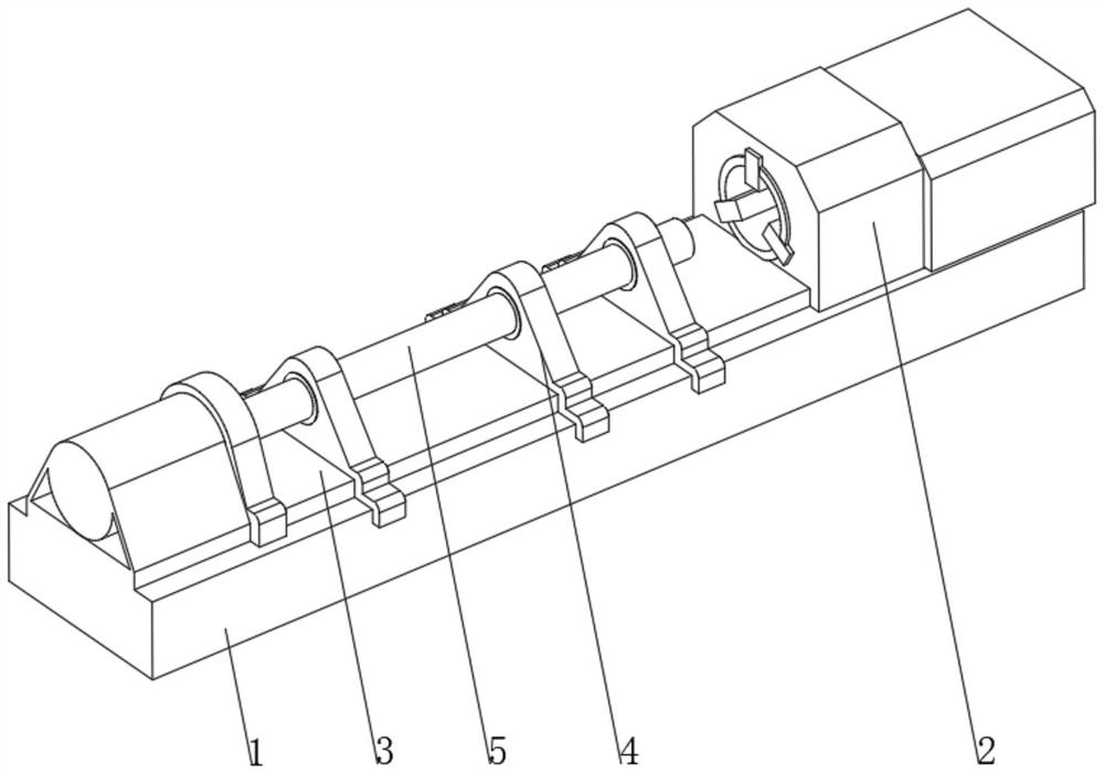
[0039] see Figure 1-2 , the present invention provides a technical solution: a deep hole boring machine with high processing precision, specifically comprising:

[0040] A boring machine base 1, the boring machine base 1 has a clamping device 2, the clamping device 2 is arranged at one end of the top of the boring machine base 2 and fixedly connected with the boring machine base 1;

[0041] Straight guide rail 3, the top of the straight guide rail 3 is provided with a support device 4, and a drill rod 5 that runs through the support device 4 and is rotatably connected to the support device 4. The end of the drill rod 5 away from the clamping device 2 is connected to an external drive device, and the support device 4 The bottom is slidingly connected with the straight guide rail 3;

[0042] The supporting device 4 includes:

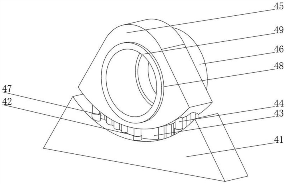
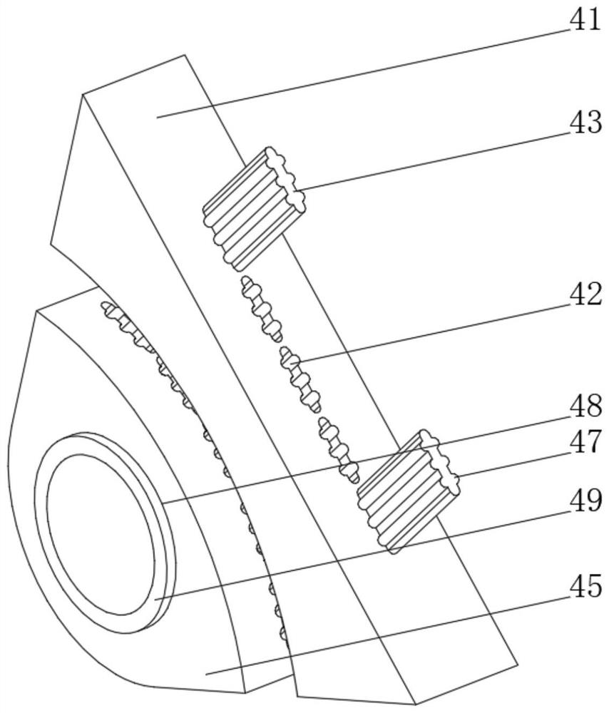
[0043] The fixed base 41, the bottom of the fixed base 41 is clamped on the straight guide rail 3 and is slidably connected with the straight guide rai...

Embodiment 2

[0048] see Figure 1-5 , on the basis of Embodiment 1, the present invention provides a technical solution: the auxiliary device 46 includes a fixed ring 461, a rotating cavity 462 is opened inside the fixed ring 461, the inner wall of the rotating cavity 462 is slidingly connected to the rotating ring 463, and the outer side of the rotating ring 463 An impact column 464 is provided, a reminder device 465 is provided on the inner wall of the rotating cavity 462, one side of the fixed ring 461 is fixedly connected with the side of the positioning seat 45, the center of the fixed ring 461 is at the same level as the center of the support hole 48, and the rotating ring is 463 sets Located on the outside of the drill rod 5 and fixedly connected with the drill rod 5, the center of the circle when the rotating ring 463 is in the initial position coincides with the center of circle of the fixed ring 461. When the drill rod 5 rotates, the drill rod 5 can drive the rotating ring 463 to ...

Embodiment 3

[0050] see Figure 1-6 , On the basis of Embodiment 1 and Embodiment 2, the present invention provides a technical solution: the reminding device 465 includes a sliding hole a1, the top of the inner wall of the sliding hole a1 is fixedly connected with an arc-shaped spring piece a2, and the bottom of the arc-shaped spring piece a2 is fixedly connected There is a toggle lever a3, one end of the toggle lever a3 extends to the inside of the rotating cavity 462 and is fixedly connected with the hammer a4, and the end of the toggle lever a3 away from the hammer a4 extends to the outside of the sliding hole a1 and is fixedly connected with the observation plate a5, The sliding hole a1 is opened on the inner wall of the rotating cavity 462, and the end of the hammer head a4 away from the toggle lever a3 faces the turning ring 463, and the parts of the inner wall of the rotating cavity 462 located on both sides of the toggle lever a3 are fixedly connected with the spring top piece 466,...


PUM


Abstract

The invention discloses a deep hole boring machine with high machining precision. The deep hole boring machine specifically comprises a boring machine base and a straight guide rail, the boring machine base is provided with a clamping device, the clamping device is arranged at one end of the top of the boring machine base and is fixedly connected with the boring machine base, and the top of the straight guide rail is provided with supporting devices and a drill rod penetrating through the supporting devices and connected with the supporting devices in a rotating mode. The bottom of each supporting device is in sliding connection with the straight guide rail, each supporting device comprises a fixed base, the bottom of each fixed base is clamped on the straight guide rail and is in sliding connection with the straight guide rail, and limiting grooves are formed in the top of each fixed base. The invention relates to the technical field of deep hole boring machines. By means of the deep hole boring machine with the high machining precision, the coaxiality between the drill rod and the supporting devices can be conveniently adjusted, adjusting operation is convenient, it can be avoided that large gaps are generated between limiting plates and the limiting grooves, it is avoided that the machining precision is affected by shaking of the drill rod, the qualified rate of workpieces can be increased, and cost is saved.

Description

technical field [0001] The invention relates to the technical field of deep hole boring machines, in particular to a deep hole boring machine with high processing precision. Background technique [0002] The deep hole drilling and boring machine is used to process deep holes with an aperture ratio of 1:6 or more, such as deep holes in parts such as gun barrels, gun barrels, and machine tool spindles. The deep hole drilling machine that rotates the workpiece (or the workpiece and the tool rotate at the same time) is similar to Horizontal lathes, deep hole drilling machines are general, special and modified from ordinary lathes. In order to facilitate cooling and chip removal, the layout of deep hole drilling machines is horizontal. The main parameter of deep hole drilling machines is the maximum drilling depth. However, the currently used horizontal deep hole boring machine drill rods are prone to eccentricity after long-term work, resulting in low precision of the processed ...

Claims


Application Information

Patent Timeline
Patent Type & Authority Applications(China)
IPC IPC(8): B23B41/02B23Q3/12B23B47/22B23B47/00B23Q11/00
CPCB23B41/02B23Q3/12B23B47/00B23Q5/26B23Q11/00Y02P70/10
Inventor 卢威
Owner 浙江省平湖市北辰实业有限公司
Learn More