Demodulation method, system and equipment for polarized light interference type optical fiber sensor

A technology of optical fiber sensor and demodulation method, which is applied in the direction of using optical devices to transmit sensing components, etc., can solve the problems of demodulation error, demodulation robustness, and poor applicability, so as to shorten the duration and improve the demodulation robustness , the effect of excellent resolution

Active Publication Date: 2021-07-09
BEIHANG UNIV
View PDF10 Cites 0 Cited by
  • Summary
  • Abstract
  • Description
  • Claims
  • Application Information

AI Technical Summary

Problems solved by technology

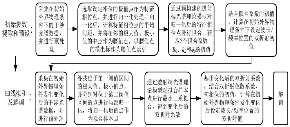
[0004] In order to solve the above problems in the prior art, that is, in order to solve the existing polarization interference optical fiber sensor demodulation scheme, the measurement range is limited by the spectral width of the light source and the demodulation error phenomenon caused by parasitic interference, resulting in demodulation robustness and applicability Poor problem, the first aspect of the present invention, proposes a kind of demodulation method that is used for polarization interference type optical fiber sensor, this method comprises:

Method used


Image

  • Demodulation method, system and equipment for polarized light interference type optical fiber sensor
  • Demodulation method, system and equipment for polarized light interference type optical fiber sensor
  • Demodulation method, system and equipment for polarized light interference type optical fiber sensor

Examples


Embodiment Construction

[0055] In order to make the purpose, technical solutions and advantages of the present invention clearer, the technical solutions in the embodiments of the present invention will be clearly and completely described below in conjunction with the accompanying drawings. Obviously, the described embodiments are part of the embodiments of the present invention, rather than Full examples. Based on the embodiments of the present invention, all other embodiments obtained by persons of ordinary skill in the art without making creative efforts belong to the protection scope of the present invention.

[0056] The application will be further described in detail below in conjunction with the accompanying drawings and embodiments. It should be understood that the specific embodiments described here are only used to explain related inventions, not to limit the invention. It should also be noted that, for the convenience of description, only the parts related to the related invention are sho...


PUM


Abstract

The invention belongs to the technical field of optical fiber sensing, particularly relates to a demodulation method, system and equipment for a polarized light interference type optical fiber sensor, and aims to solve the problems that the measurement range of an existing polarized light interference type optical fiber sensor demodulation scheme is limited by the spectral width of a light source, demodulation errors are caused by parasitic interference, and poor the demodulation robustness and applicability are caused. The method comprises the steps: acquiring interference spectrum data under an initial external physical condition; selecting an extreme point of a set phase and carrying out normalization processing; obtaining an initial value of a fitting coefficient; calculating a birefringence initial value of a set wavelength / frequency position under an initial external physical condition; collecting interference spectrum data after the initial external physical condition is changed; selecting fitting sample points by using waist value points; carrying out least square fitting; calculating a birefringence value of a set wavelength / frequency position after the initial external physical condition changes; and calculating the difference between the birefringence values and demodulating. According to the invention, the demodulation robustness and applicability are improved.

Description

technical field [0001] The invention belongs to the technical field of optical fiber sensing, and in particular relates to a demodulation method, system and equipment for polarization interference optical fiber sensors. Background technique [0002] The common polarization-maintaining optical fiber sensor sensing unit is a polarization-maintaining fiber. When light is transmitted along the fast axis and slow axis of the polarization-maintaining fiber, the phase difference will be generated due to the birefringence of the polarization-maintaining fiber. When the physical conditions such as gas pressure and hydrogen concentration change, the birefringence value of the sensing fiber changes, which will cause the phase difference of the two polarization modes to change, resulting in different degrees of shift in the overall polarization interference spectrum. By detecting the interference spectrum The measurement of the physical quantity can be realized by shifting or sensing th...

Claims


Application Information

Patent Timeline
IPC IPC(8): G01D5/353
CPCG01D5/353
Inventor 杨远洪李慧王子垚
Owner BEIHANG UNIV
Why Eureka
Try Eureka