
New energy vehicle battery placing device

A new energy vehicle and battery placement technology, which is applied to battery pack components, circuits, trolleys, etc., can solve the problems of cost waste and battery damage, and achieve the effect of protecting new energy vehicle batteries, buffering and shock absorbing new energy vehicle batteries

Active Publication Date: 2021-07-09
苏州特瑞菲机械设备有限公司
View PDF13 Cites 4 Cited by
  • Summary
  • Abstract
  • Description
  • Claims
  • Application Information

AI Technical Summary

Problems solved by technology

[0004] In order to overcome the shortcomings of collisions during transportation, damage to the battery, and waste of cost, the technical problem is to provide a new energy vehicle battery placement device that is easy to disassemble and install, and can effectively protect the new energy vehicle battery.

Method used


Image

  • New energy vehicle battery placing device
  • New energy vehicle battery placing device
  • New energy vehicle battery placing device

Examples


Embodiment 1

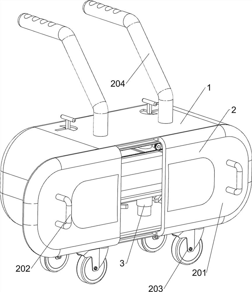
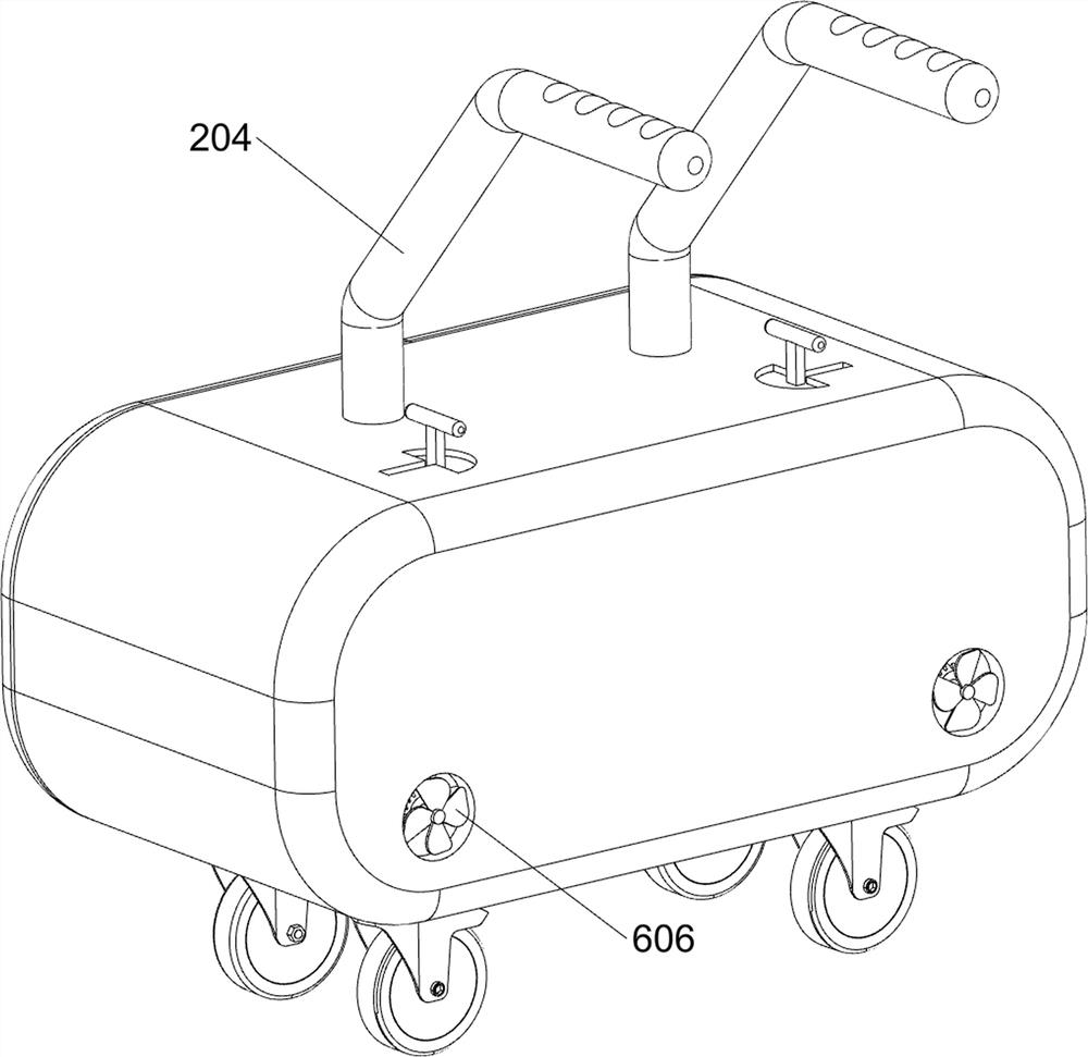
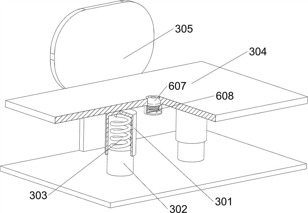
[0025] A new energy vehicle battery placement device, such as Figure 1-Figure 3 As shown, a placement box 1, a push assembly 2 and a placement assembly 3 are included, the placement box 1 is provided with a push assembly 2, and the placement box 1 is provided with a placement assembly 3.

[0026] First, people open the pushing component 2 of the placement box 1, and then the new energy vehicle battery is placed on the placement component 3, and after the pushing component 2 is closed, people push the pushing component 2, and the new energy vehicle battery can be transported and stored to protect the new energy. The effect of car batteries.

[0027] The push assembly 2 includes a protective door 201, a handle 202, a universal wheel 203 and a first push rod 204; Universal wheels 203 are arranged on the bottom symmetrically rotating type, and first push rods 204 are arranged symmetrically on the top of the placement box 1 .

[0028] The placement assembly 3 includes a cylindri...

Embodiment 2

[0031] On the basis of Example 1, such as Figure 4-Figure 7 As shown, the clamping assembly 4 is also included. The clamping assembly 4 includes a first connecting rod 401, a clamping block 402, a second spring 403, a special-shaped rod 404 and a clamping rod 405. For the first connecting rod 401, a clamping block 402 is provided between the first connecting rod 401 on the same side, and a second spring 403 is connected between the clamping block 402 and the storage box 1, and the second springs 403 are respectively set on the first connecting rod On 401, special-shaped rods 404 are provided on the outside of the clamping block 402, and clamping rods 405 are provided on the top of the special-shaped rods 404.

[0032] When people need to place the new energy vehicle battery on the placement plate 304, they first pull the clamp block 402 outward, the first connecting rod 401 moves outward, the second spring 403 is squeezed, and then the new energy vehicle battery is placed on ...


PUM


Abstract

The invention relates to a placing device, in particular to a new energy vehicle battery placing device. The technical problem is to provide the new energy vehicle battery placing device which is convenient to disassemble and assemble and can effectively protect a new energy vehicle battery. According to the technical scheme, the new energy vehicle battery placing device comprises a containing box and a pushing assembly, and the pushing assembly is arranged on the containing box; and a placing assembly which is arranged on the placing box. Firstly, a user pulls a handle to open protective doors on the two sides, then a new energy vehicle battery is placed on a placing plate, a fixing plate limits the new energy automobile battery, a cylindrical groove moves downwards due to the weight of the new energy automobile battery, and meanwhile, in order to prevent high-temperature weather from affecting the performance of the energy vehicle battery, a double-shaft motor is started to enable a fan to rotate to be matched with a ventilation opening opened by a check block to discharge heat in the placement box, heat dissipation and cooling are conducted, and the effects of buffering, damping and protecting the new energy vehicle battery are achieved.

Description

technical field [0001] The invention relates to a placing device, in particular to a new energy vehicle battery placing device. Background technique [0002] With the development of science and technology, the application of new energy vehicles is becoming more and more popular. In new energy vehicles, batteries are the main source of power. During the production and transportation of new energy vehicle batteries, it is necessary to protect and transport new energy vehicle batteries to prevent new energy vehicles. The damage to the battery of the energy vehicle causes unnecessary waste. However, the existing placement device is relatively simple at present. When disassembling the battery of the new energy vehicle, the steps are relatively cumbersome and it is easy to take out the failure to damage the battery; The battery of energy vehicles collides during the transfer, which damages the battery and causes waste of cost. [0003] Therefore, it is necessary to design a new e...

Claims


Application Information

Patent Timeline
Patent Type & Authority Applications(China)
IPC IPC(8): B62B3/00B62B3/04B62B5/00H01M50/244H01M50/242
CPCB62B3/005B62B3/04B62B5/0006B62B2202/61Y02E60/10
Inventor 雷桂香
Owner 苏州特瑞菲机械设备有限公司
Learn More