Miniaturized double-frequency microstrip array antenna
A technology of microstrip arrays and antennas, applied in antennas, antenna arrays, electrical components, etc., can solve problems such as inability to adapt to use requirements, inability to change forms, troublesome deployment and recycling, etc.
- Summary
- Abstract
- Description
- Claims
- Application Information
AI Technical Summary
Problems solved by technology
Method used
Image

Examples
Embodiment 1
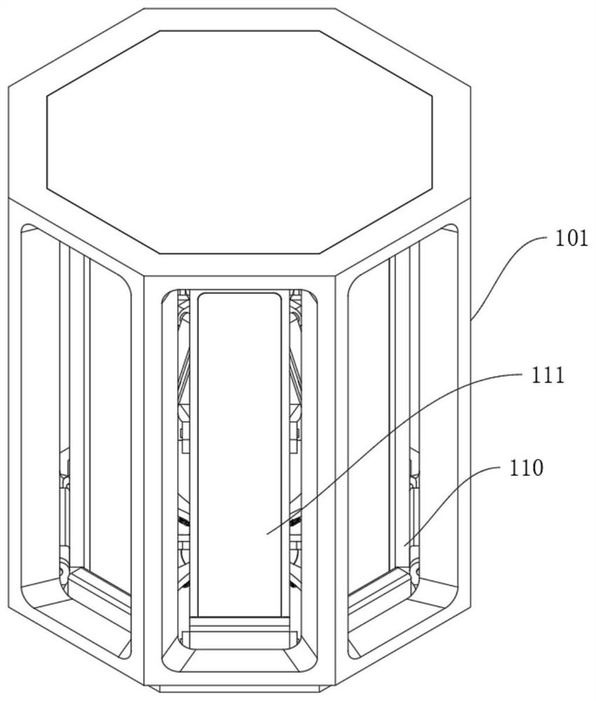
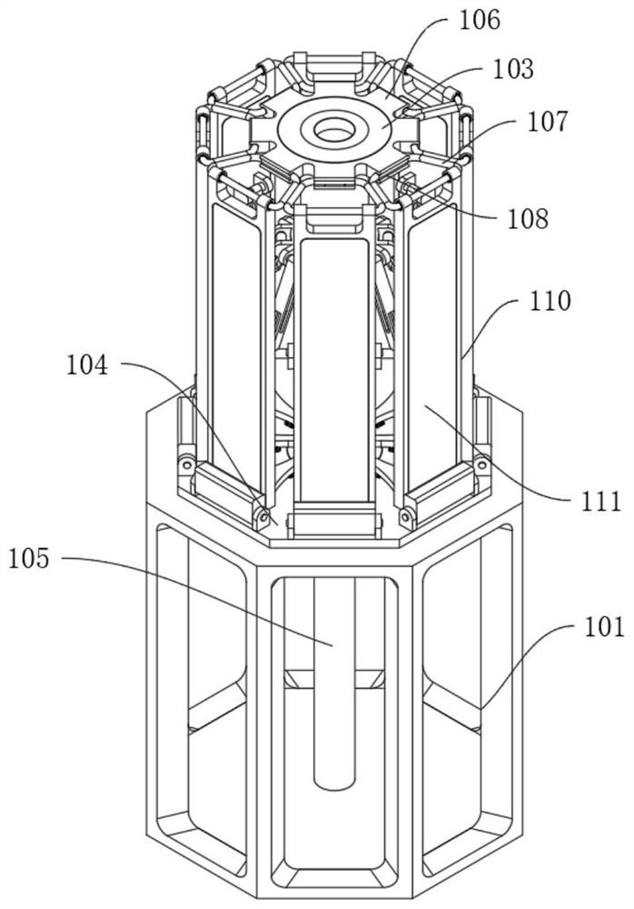
[0026] refer to Figure 1-4 , a miniaturized dual-frequency microstrip array antenna, comprising: a mobile base 101, a support column 102, a support chassis 103 and a pressure-bearing chassis 104; The inner bottom side of the support column 102 is in contact with the inner upper surface of the expansion limiting mechanism, and the upper end of the support column 102 is fixedly connected with the inner shaft center of the support chassis 103. The support chassis 103 is ring-mounted and fixedly installed with 8 sets of embedded installation blocks 106, The embedded installation block 106 is provided with an embedded groove 108 that matches the snap-in rod 107, and the inner side of the snap-in rod 107 is movably socketed inside the embedded groove 108, and two groups of snap-in rods 107 are fixedly installed on the outer side The torsion spring 109, the other end of the torsion spring 109 is fixedly connected to the left and right sides of the upper end of the rotating protectiv...
Embodiment 2
[0030] Embodiment 2: Based on Embodiment 1, but different again is;
[0031] The upper and lower sides of the inside of the embedded groove 108 are located at the left and right sides of the middle part to be provided with limiting grooves 201, and the upper and lower sides of the inside of the clamping rod 106 are arranged with fixed grooves 202 at the left and right sides of the middle part. The upper end of 203 is fixedly connected with the inner end of the clamping block 204 , the clamping block 204 is movably socketed inside the fixing groove 202 , and the clamping block 204 matches with the limiting groove 201 .
[0032]During use, an embedded installation block 106 is also provided on the support chassis 103. By using modular installation, when a certain dual-frequency microstrip array antenna module 111 is damaged, it can be replaced by modular installation. Pull out the snap-in rod 107 externally to separate the snap-in rod 107 from the insertion groove 108, and then ...
Embodiment 3
[0033] Embodiment 3: based on Embodiment 1 and 2, but different again is;
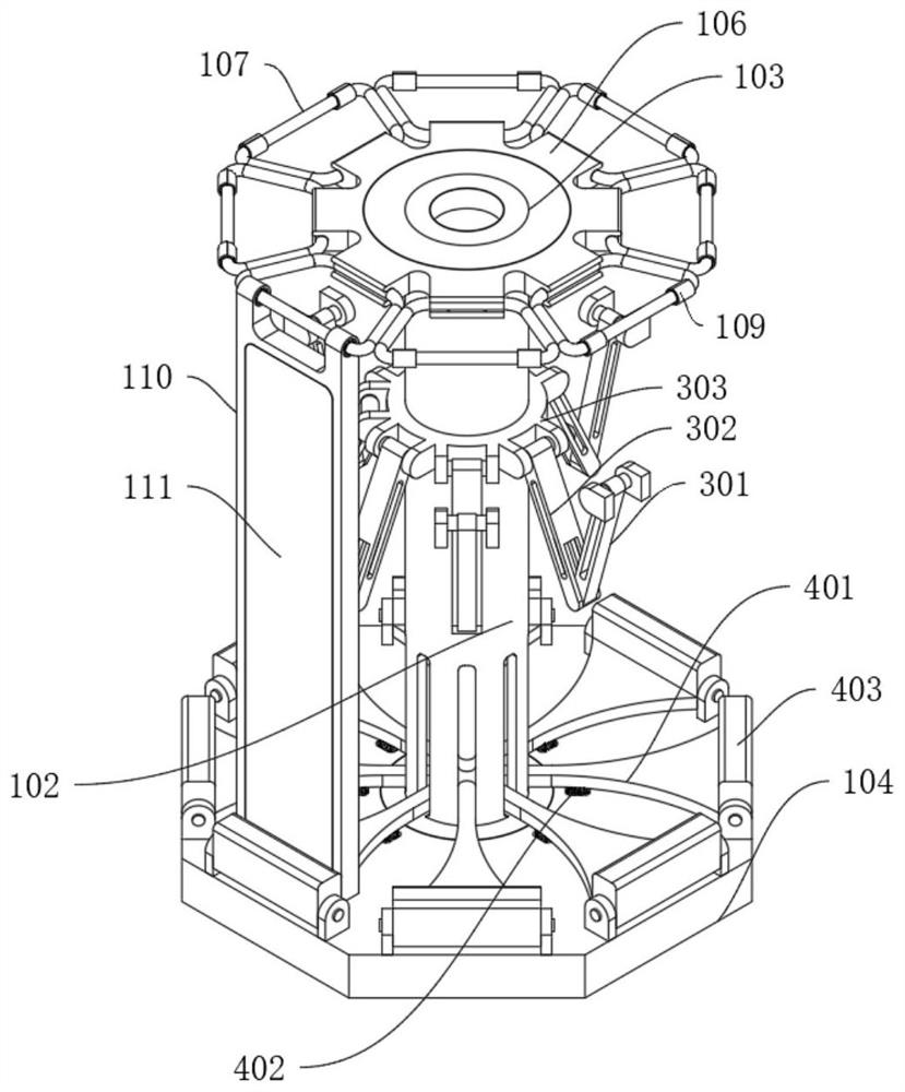
[0034] The deployment buffer mechanism includes: a rotating rod 301, a linkage rod 302, and a fixed base 303. The rear middle part of the dual-frequency microstrip array antenna module 111 is movably connected to the outer end of the rotating rod 301 through a rotating shaft, and the inner end of the rotating rod 301 is connected to the linkage rod. The outer end of 302 is movably connected through the rotating shaft, and the inner end of the linkage rod 302 is movably connected with the outer side of the fixed base 303 through the rotating shaft, and the fixed base 303 is fixedly sleeved on the support column 102 .
[0035] The expansion limiting mechanism includes: a rotating plate 401, a limit spring 402 and an anti-collision plate 403. The lower end of the pressure bearing rod 105 is movably connected with the upper surface on the inner side of the rotating plate 401. The rotating plate 401 is provi...
PUM
 Abstract
Description
Claims
Application Information
 - R&D
- Intellectual Property
- Life Sciences
- Materials
- Tech Scout
- Unparalleled Data Quality
- Higher Quality Content
- 60% Fewer Hallucinations
Browse by: Latest US Patents, China's latest patents, Technical Efficacy Thesaurus, Application Domain, Technology Topic, Popular Technical Reports.
© 2025 PatSnap. All rights reserved.Legal|Privacy policy|Modern Slavery Act Transparency Statement|Sitemap|About US| Contact US: help@patsnap.com