
Convenient water collecting and draining device for deep foundation pit

A drainage device and a portable technology, which is applied in drainage devices, water collection and drainage devices, and deep foundation pits in the field of convenient water collection. It can solve the problems of pump burnout, loose interstitial water, and complicated process.

Inactive Publication Date: 2021-07-06
CHINA RAILWAY CONSTR ENG GROUP
View PDF3 Cites 0 Cited by
  • Summary
  • Abstract
  • Description
  • Claims
  • Application Information

AI Technical Summary

Problems solved by technology

[0002] With the rapid development of my country's construction industry, brick wells or direct submersible pumps are usually used for the drainage of deep foundation pits. The pumps are often stuck and burned due to sediment and debris in the water. Cannot collect and drain water effectively, not only the drainage efficiency is low, the technological process is complicated, but also the manual maintenance cost is high
[0003] Sometimes the excavation depth of the foundation pit will reach 11m, but in the case of large site area, low terrain, and uncertain groundwater position, it is easy to cause the water level of the foundation pit to be unable to drop to the effective water level at one time. When the geological conditions are mainly silty clay , the foundation pit is easy to become loose after being exposed to water and the interstitial water is abundant. How to keep the foundation pit dry and avoid the sewage operation of the foundation pit is an important problem in the construction of the foundation pit

Method used


Image

  • Convenient water collecting and draining device for deep foundation pit
  • Convenient water collecting and draining device for deep foundation pit
  • Convenient water collecting and draining device for deep foundation pit

Examples


Embodiment Construction

[0025] The present invention is described in further detail now in conjunction with accompanying drawing. These drawings are all simplified schematic diagrams, which only illustrate the basic structure of the present invention in a schematic manner, so they only show the configurations related to the present invention.

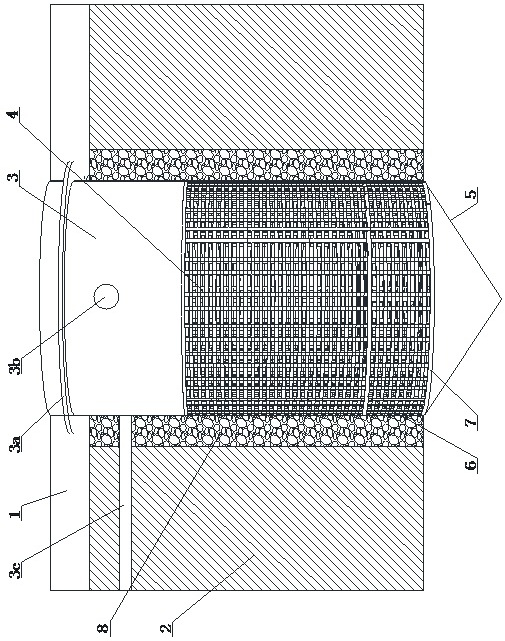
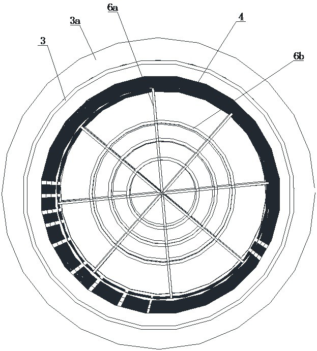
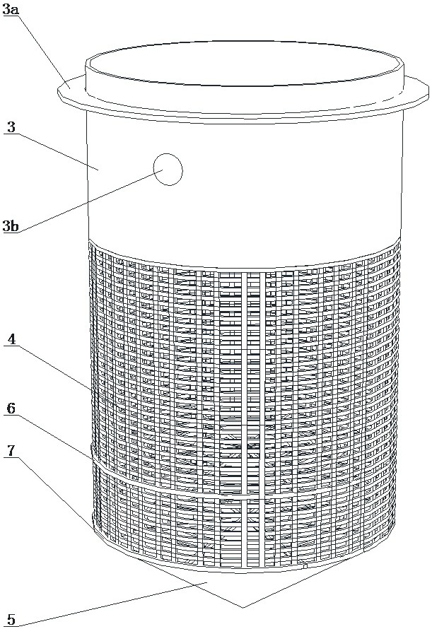
[0026] Such as Figure 1 to Figure 3 As shown, the deep foundation pit portable water collection and drainage device of the present invention comprises a concrete cushion 1, and the concrete cushion 1 is poured on the top of the foundation pit soil 2, and the foundation pit soil 2 is provided with a sump, and the sump There is a water collection tube in the middle, and the upper part of the water collection tube is a plastic light pipe 3, the upper port of the plastic light pipe 3 is not lower than the upper surface of the concrete cushion 1, and a hollow cylindrical grid 4 is connected to the bottom of the plastic light pipe 3.

[0027] The lower end of the ...


PUM


Abstract

The invention relates to a convenient water collecting and draining device for a deep foundation pit, and belongs to the technical field of civil engineering. The convenient water collecting and draining device for the deep foundation pit comprises a concrete cushion layer, wherein the concrete cushion layer is poured above foundation pit soil, a water collecting pit is arranged in the foundation pit soil, a water collecting barrel is arranged in the water collecting pit, a plastic light pipe is arranged on the upper part of the water collecting barrel, an upper end opening of the plastic light pipe is not lower than the upper surface of the concrete cushion layer, and the lower part of the plastic light pipe is connected with a hollow-out barrel-shaped grating; the lower end of the barrel-shaped grating is connected with a conical bottom which is of a hollow structure, and the center of the conical bottom is sunken downwards; a hollow-out water pump placing bearing platform is arranged on the lower part of an inner cavity of the barrel-shaped grating, and a hollow-out bottom bearing platform is arranged at a lower end opening of the barrel-shaped grating; a water stop ring embedded in the concrete cushion layer is arranged on the periphery of the upper part of the plastic light pipe, and a plurality of drainage openings are formed in the circumference of the plastic light pipe. According to the convenient water collecting and draining device for the deep foundation pit, large silt in the foundation pit can be effectively isolated, seepage water is effectively filtered out, the service life of a water pump is prolonged, the drainage efficiency is improved, the maintenance cost is reduced, and the foundation pit is kept dry when the geological condition is silty clay.

Description

technical field [0001] The invention relates to a water collection and drainage device, in particular to a convenient water collection and drainage device for deep foundation pits, belonging to the technical field of civil engineering construction devices. Background technique [0002] With the rapid development of my country's construction industry, brick wells or direct submersible pumps are usually used for the drainage of deep foundation pits. The pumps are often stuck and burnt due to sediment and debris in the water. It cannot effectively collect and drain water, not only the drainage efficiency is low, the process is complicated, but also the manual maintenance cost is high. [0003] Sometimes the excavation depth of the foundation pit will reach 11m. However, when the site area is large, the terrain is low, and the location of groundwater is uncertain, it is easy to cause the water level of the foundation pit to be unable to drop to the effective water level at one ti...

Claims


Application Information

Patent Timeline
IPC IPC(8): E02D19/06E02D19/10E02D19/22B01D29/35B01D29/94B01D36/04
CPCE02D19/06E02D19/10E02D19/22B01D29/35B01D29/94B01D36/04
Inventor 陆剑峰芮兴龙郑奎智孙泽昌李超吴贞赞刘祖志曹晓帆张健张骥李轩马伟李苏畅程军周华嵘陈翔孙涛涛李为宝王佳玺谭蛟王道欣吕朝阳李永达
Owner CHINA RAILWAY CONSTR ENG GROUP
Learn More