
Anti-backflow perforated aerator

A perforated aeration and anti-backflow technology, applied in water aeration, chemical instruments and methods, biological water/sewage treatment, etc., can solve the problems of internal blockage of aeration devices, increase of air supply, fusion and other problems

Active Publication Date: 2021-07-06
镇江伊博特环保科技有限公司
View PDF8 Cites 0 Cited by
  • Summary
  • Abstract
  • Description
  • Claims
  • Application Information

AI Technical Summary

Problems solved by technology

[0008] 4) When the water quality changes greatly, the demand for oxygen supply and stirring often changes in different proportions. Often, the demand for oxygen supply changes greatly, while the demand for stirring changes slightly. Therefore, when corresponding to a small demand for oxygen supply, The stirring effect will not meet the requirements. At this time, in order to ensure the stirring effect, the air supply can only be increased, which will increase the power consumption of aeration; if the air is supplied according to the oxygen supply demand, the stirring effect will not meet the standard. Bringing problems such as sedimentation and clogging of the aerator as mentioned above
[0010] 1) The number of openings of the rubber membrane microporous aerator is small and the air outlet diameter is large, resulting in a low oxygen transfer rate of the rubber membrane microporous aerator. At the same time, the rubber membrane microporous aerator is a closed-cell aerator For the device, before the air is released, the hole needs to be opened first, so the air outlet resistance of the rubber membrane microporous aerator is relatively large, the low oxygen transfer rate and the high air outlet resistance lead to the inflation of the rubber membrane microporous aerator. The oxygen dynamic efficiency is low, and the direct impact is the high power consumption of aeration
[0011] 2) Perforated aerators such as corundum and polyethylene have small air outlet apertures and a large number. Theoretically, the oxygen transfer rate of this type of aerator should be high, but the layout of the holes of this type of aerator is caused by the type of opening. Disorganized, the distance between holes is too small, resulting in the fusion of air bubbles and uneven air outlet, and the air bubbles are not all small air bubbles, which in turn affects the oxygen transfer rate of this type of aerator. Therefore, in practical applications, The oxygen transfer rate of perforated aerators made of corundum and polyethylene is not significantly improved compared with rubber membrane closable aerators
[0013] 1) Perforated aerators such as corundum and polypropylene have technical defects in that sewage flows back into the aeration device after the gas is stopped, so this type of aeration device is prone to internal blockage
[0014] 2) Because the sewage contains a large amount of inorganic matter, organic matter and microorganisms, external plugging is an unavoidable problem for materials such as ceramics (corundum), rubber diaphragms and polyethylene
[0015] 3) Blockage leads to increased air outlet resistance and increased aeration power consumption
[0016] 4) The blockage leads to an increase in air outlet resistance, which increases the probability of damage to the vulnerable parts of the aeration device. Among them, the rubber membrane microporous aerator is densely covered with small holes in the rubber aeration diaphragm, and the strength of the rubber itself is not high, resulting in rubber aeration. Diaphragm is more prone to tearing
Once the aeration device is damaged, it is very difficult to repair because it works underwater, and often needs to stop production for maintenance

Method used


Image

  • Anti-backflow perforated aerator
  • Anti-backflow perforated aerator
  • Anti-backflow perforated aerator

Examples


Embodiment Construction

[0053] In order to illustrate the present invention more clearly, the present invention will be further described below in conjunction with preferred embodiments. Those skilled in the art should understand that the content specifically described below is illustrative rather than restrictive, and should not limit the protection scope of the present invention.

[0054] In describing the present invention, it is to be understood that the terms "center", "upper", "lower", "front", "rear", "left", "right", "vertical", "horizontal", The orientations or positional relationships indicated by "top", "bottom", "inner", "outer", etc. are based on the orientations or positional relationships shown in the drawings, and are only for the convenience of describing the present invention and simplifying the description, rather than indicating or implying the It should not be construed as limiting the invention that a device or element must have a particular orientation, be constructed, and oper...


PUM


Abstract

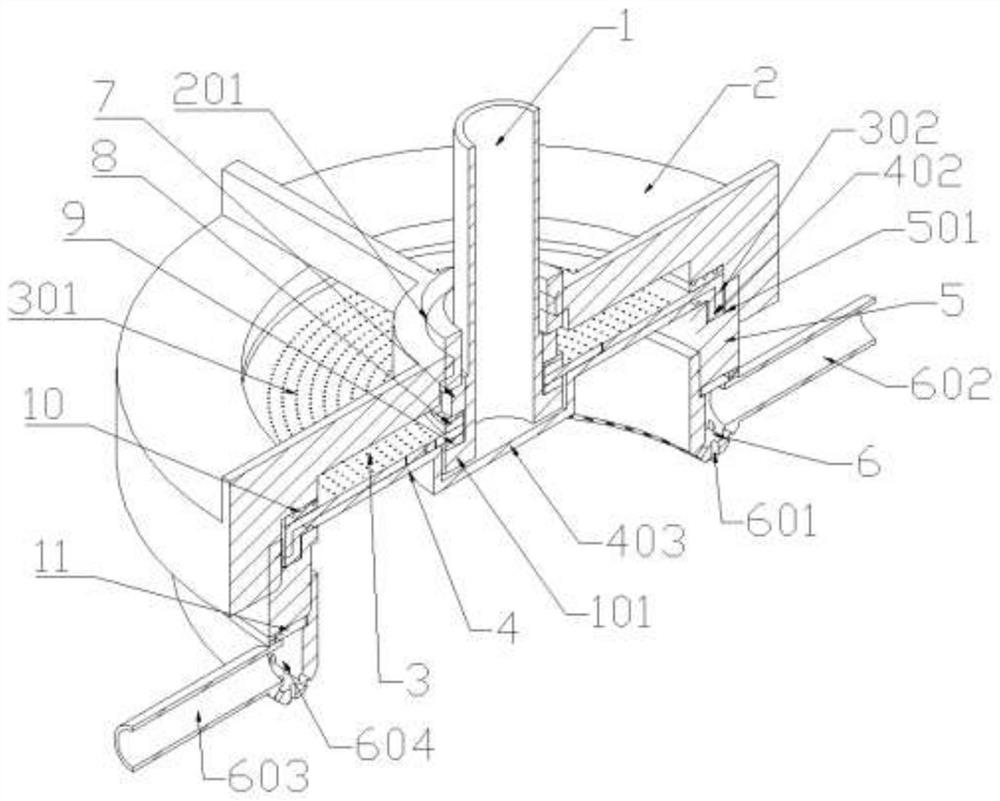
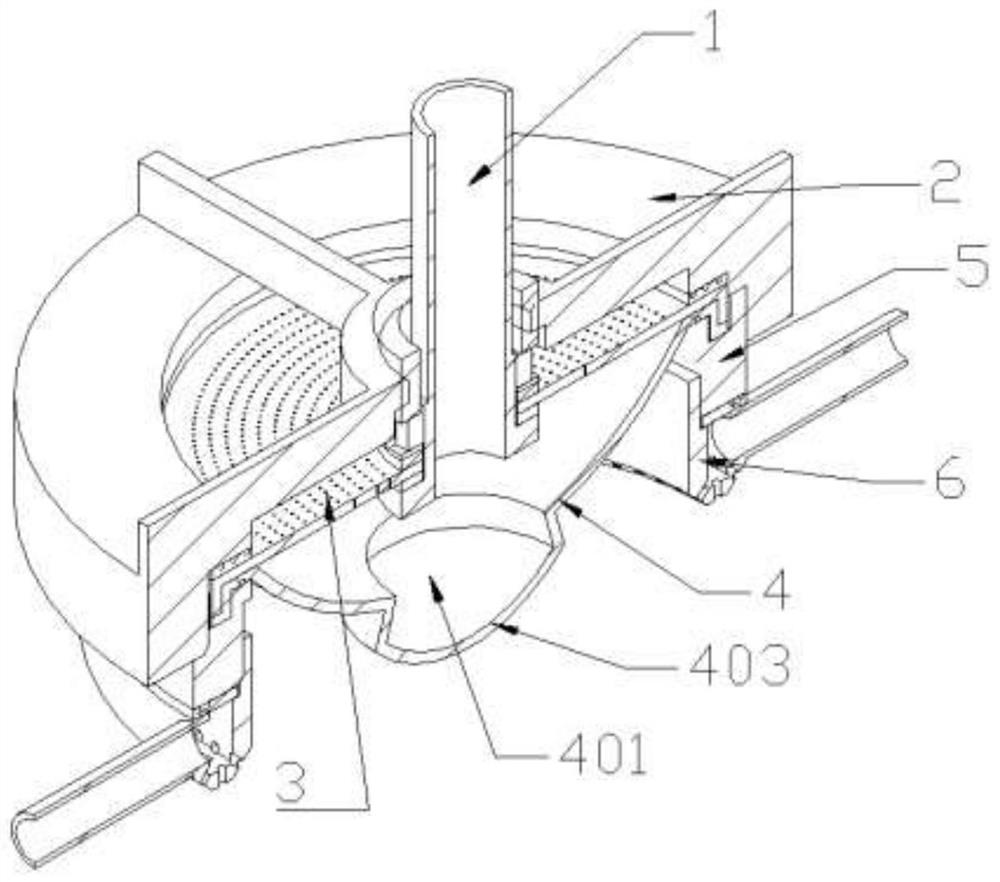
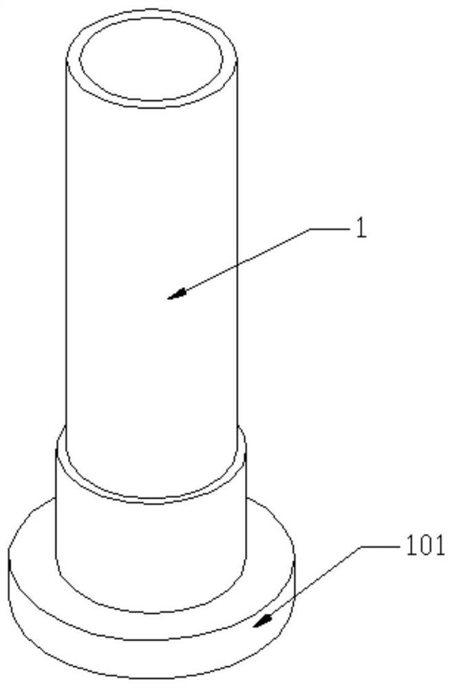
The invention relates to the technical field of environmental protection equipment, and discloses an anti-backflow perforated aerator, which comprises an air inlet pipe, a clamping device, an oxygen supply aeration diaphragm, an anti-backflow rubber diaphragm, a locking ring and a pressing cover, wherein the oxygen supply aeration diaphragm is in a circular ring shape, oxygen supply aeration holes are formed in the ring surface of the oxygen supply aeration diaphragm at equal intervals, a boss is arranged at the bottom of the air inlet pipe, the inner ring of the oxygen supply aeration diaphragm is clamped between the clamping device and the boss, the anti-backflow rubber diaphragm is arranged below the oxygen supply aeration diaphragm and is provided with a groove matched with the boss, and the outer ring of the oxygen supply aeration diaphragm and the outer ring of the anti-backflow rubber diaphragm abut against each other and are fixedly clamped between the locking ring and the pressing cover. According to the invention, the oxygen supply function and the stirring function can work independently and can also work cooperatively, and the oxygen supply power efficiency and stability are greatly improved.

Description

technical field [0001] The invention relates to the technical field of environmental protection equipment, in particular to an anti-backflow perforated aerator. Background technique [0002] Aeration is the main production process of activated sludge treatment of wastewater, and its purpose is to achieve oxygen supply to bacteria and agitation of sludge. In the aeration link, most sewage treatment plants adopt the blast aeration type, and the aeration device is the core component of the blast aeration system. At present, the most common blast aeration device is a microporous aerator. [0003] There are many classification methods for microporous aerators, which can be divided into: ceramic (corundum), rubber diaphragm and polyethylene, etc. according to the material; according to the structure, it can be divided into: plate type, disc type and tube type, etc. According to whether the hole can be closed when the gas is stopped, it can be divided into: perforated aerator and ...

Claims


Application Information

Patent Timeline
IPC IPC(8): C02F3/12C02F7/00
CPCC02F3/1278C02F7/00C02F2203/006C02F2201/005Y02W10/10
Inventor 劳森朱长顺
Owner 镇江伊博特环保科技有限公司
Learn More