


Quick Research
Generate reliable direction feasibility study reports for your R&D in just a few steps.

Technical Q&A
Discover and master advanced knowledge NOW. Basics, ideas, possibilities, all at once.

Find Solutions
As an expert in R&D theories, this can generate solutions to your technical problems instantly.

Evaluate Feasibility
Analyze your overall solution with one click, know your potential R&D risks in advance.

Monitor Landscape
Get weekly tech updates, stay abreast of the latest tech innovations and key insights.
Polyurethane continuous plate cutting device for rock wool composite insulation board production
A composite thermal insulation and continuous board technology, applied in metal processing and other directions, can solve the problem of inconvenient collection of polyurethane boards
- Summary
- Abstract
- Description
- Claims
- Application Information
AI Technical Summary
Problems solved by technology
Method used
Image

Examples
Embodiment 1
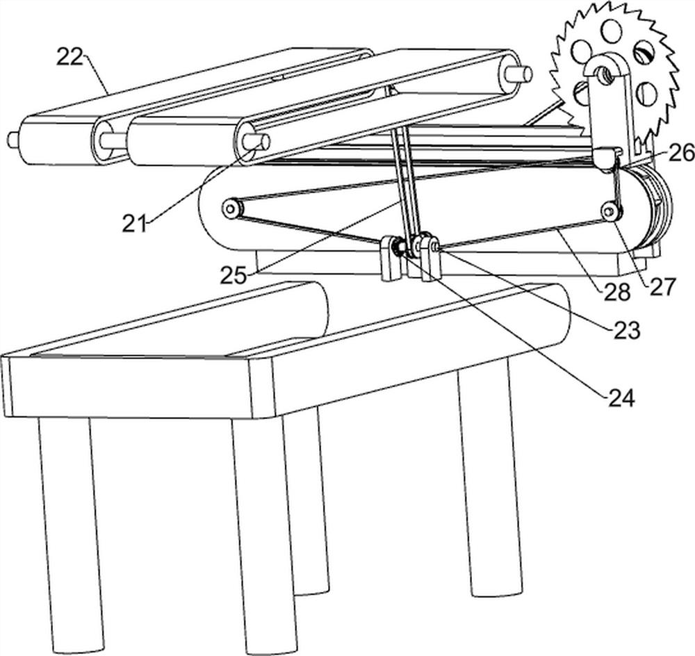
[0031] A polyurethane continuous board dividing device for rock wool composite insulation board production, such as figure 1 , figure 2 , image 3 , Figure 4 and Figure 5 As shown, it includes a base 1, a worktable 2, a sliding table 3, a moving device 4 and a cutting device 5; There is a mobile device 4 on which a cutting device 5 is arranged.
[0032] When people need to use this device, people first place the polyurethane board on the workbench 2, and then start the mobile device 4, so that the mobile device 4 drives the cutting device 5 to operate, and then the cutting device 5 moves back and forth to cut the polyurethane board , so that people only need to push the polyurethane board to the left to cut the polyurethane board quickly, and when people do not need to use the device, the mobile device 4 can be closed.
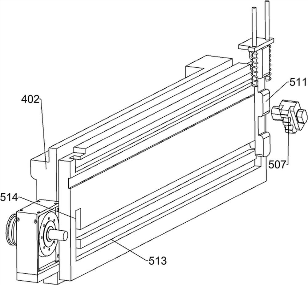
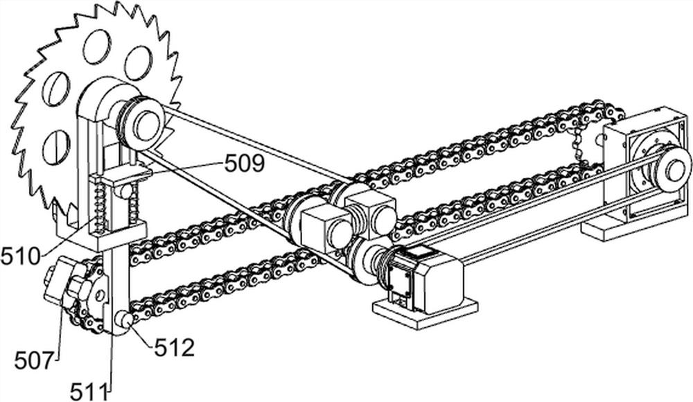
[0033]The mobile device 4 includes a fixed platform 401, a first fixed plate 402, a sliding mounting seat 403, a first rotating shaft 404, circular sa...
Embodiment 2
[0037] On the basis of Example 1, such as Image 6 , Figure 7 , Figure 8 and Figure 9 As shown, it also includes a second mounting plate 6, a wedge block 7, a special-shaped extrusion block 8, a guide shaft 9, a first sliding block 10, a third elastic member 11, a guide groove plate 12, a second sliding block 13 and a second sliding block 13. Four elastic parts 14, the second mounting plate 406 top is provided with the second mounting plate 6, and the symmetrical sliding type on the second mounting plate 6 is provided with wedge-shaped block 7, and the wedge-shaped block 7 is all provided with special-shaped extruding block 8, and special-shaped extruding The block 8 slides in the second mounting plate 6, and the special-shaped extruding block 8 cooperates with the top block 509. The left side of the second mounting plate 6 is symmetrically provided with a guide shaft 9, and the wedge-shaped block 7 is provided with a first sliding block 10. A sliding block 10 slides on ...
PUM
 Abstract
Description
Claims
Application Information
 - R&D Engineer
- R&D Manager
- IP Professional
- Industry Leading Data Capabilities
- Powerful AI technology
- Patent DNA Extraction
Browse by: Latest US Patents, China's latest patents, Technical Efficacy Thesaurus, Application Domain, Technology Topic, Popular Technical Reports.
© 2024 PatSnap. All rights reserved.Legal|Privacy policy|Modern Slavery Act Transparency Statement|Sitemap|About US| Contact US: help@patsnap.com