Weeding device for agricultural planting

An agricultural, work box technology, applied in the direction of agriculture, spraying devices, agricultural machinery and implements, etc.

Pending Publication Date: 2021-07-06
王秀军
View PDF12 Cites 0 Cited by
  • Summary
  • Abstract
  • Description
  • Claims
  • Application Information

AI Technical Summary

Problems solved by technology

[0004] The purpose of the present invention is to solve the shortcomings of the existing weed-killing device for agricultural planting, which does not have the function of stirring the herbicide and water when weeding, and does not have the function of collecting and pulverizing the removed grass, and proposes a Weeding device for agricultural planting

Method used


Image

  • Weeding device for agricultural planting
  • Weeding device for agricultural planting
  • Weeding device for agricultural planting

Examples


Embodiment 1

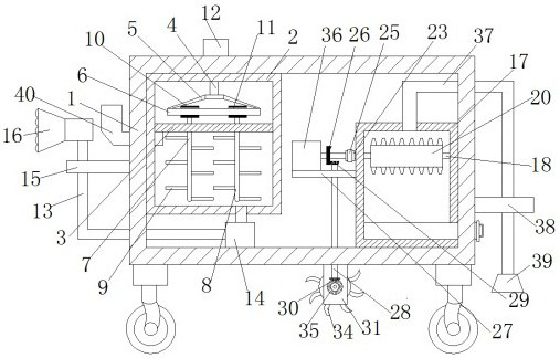
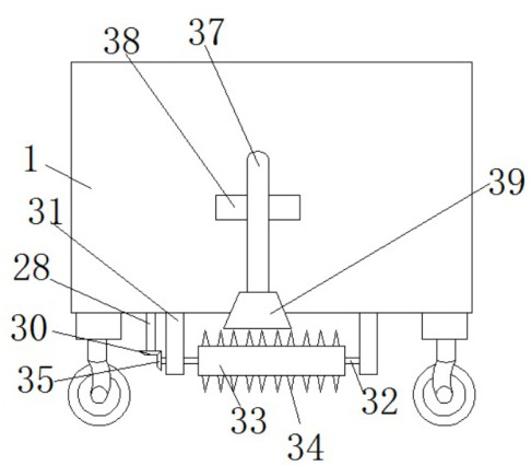
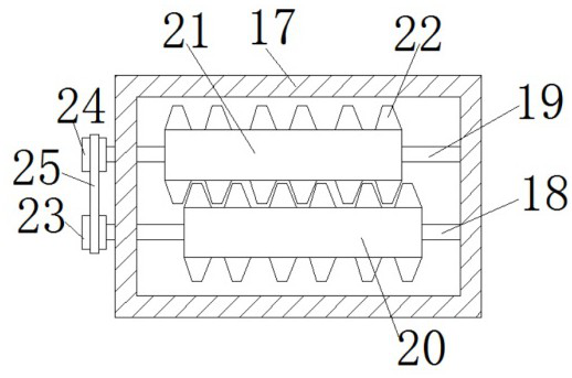
[0028] refer to Figure 1-5 , a weeding device for agricultural planting, comprising a work box 1, a mixing and spraying mechanism and a crushing mechanism are provided in the work box 1, a weeding mechanism is provided at the bottom of the work box 1, and the stirring and spraying mechanism includes a stirring box 2, a dividing plate 3 , drive rotating rod 4, rotating frame 5, tooth steel ring 6, first stirring rod 7, second stirring rod 8, two stirring blades 9, first gear 10, second gear 11, stirring motor 12, chemical spraying Pipe 13, spraying pump 14, branch tube plate 15 and nozzle 16, mixing box 2 is located in working box 1, mixing box 2 is fixedly connected to working box 1, partition 3 is fixedly connected to mixing box 2, and driving rotating rod 4 is connected to working box 1 and the top of the mixing box 2 are rotationally connected, the rotating frame 5 is fixedly connected to one end of the driving rotating rod 4, the toothed steel ring 6 is fixedly connected ...

Embodiment 2

[0039] refer to Figure 1-5 , a weeding device for agricultural planting, comprising a work box 1, a mixing and spraying mechanism and a crushing mechanism are provided in the work box 1, a weeding mechanism is provided at the bottom of the work box 1, and the stirring and spraying mechanism includes a stirring box 2, a dividing plate 3 , drive rotating rod 4, rotating frame 5, tooth steel ring 6, first stirring rod 7, second stirring rod 8, two stirring blades 9, first gear 10, second gear 11, stirring motor 12, chemical spraying Pipe 13, spraying pump 14, branch tube plate 15 and nozzle 16, mixing box 2 is located in working box 1, mixing box 2 is welded to working box 1, partition 3 is welded to mixing box 2, and driving rotating rod 4 is connected to working box 1 and the top of the mixing box 2 are rotationally connected, the rotating frame 5 is welded to one end of the driving rotating rod 4, the toothed steel ring 6 is welded to the rotating frame 5, and the first stirr...


PUM


Abstract

The invention belongs to the technical field of weeding, crushing and stirring, and particularly relates to a weeding device for agricultural planting. Aiming at the problems that an existing weeding device for agricultural planting does not have a function of stirring herbicide and water during weeding and does not have a function of collecting and crushing removed grasses, the invention provides the following scheme that the weeding device for agricultural planting comprises a working box, wherein a stirring and herbicide spraying mechanism and a smashing mechanism are arranged in the working box; a weeding mechanism is arranged at the bottom of the working box; the stirring and herbicide spraying mechanism comprises a stirring box, a partition plate, a driving rotating rod, a rotating frame, a tooth steel ring, a first stirring rod, a second stirring rod, two stirring blades, a first gear, a second gear, a stirring motor, a herbicide spraying pipe, a herbicide spraying pump, a branch pipe plate and a spraying head; the stirring box is located in the working box; the stirring box is fixedly connected with the working box; and the partition plate is fixedly connected with the stirring box. The weeding device for agricultural planting provided by the invention is simple in structure, can stir the liquid herbicide and crush the removed grasses, and is convenient for people to use.

Description

technical field [0001] The invention relates to the technical field of weeding, crushing and stirring, in particular to a weeding device for agricultural planting. Background technique [0002] In the process of agricultural planting, weeds compete with crops for soil moisture and nutrients, occupy farmland space, and affect crop growth. This not only reduces the yield and quality of crops, but also indirectly promotes the breeding and spread of pests and diseases. Generally, it is necessary to regularly use a weeding device to clean up weeds to ensure the growth quality of crops. [0003] The existing weeding devices for agricultural planting do not have the function of stirring the herbicide and water when weeding, and do not have the function of collecting and pulverizing the removed grass. Contents of the invention [0004] The purpose of the present invention is to solve the shortcomings of the existing weed-killing device for agricultural planting, which does not ha...

Claims


Application Information

Patent Timeline
IPC IPC(8): A01D43/10A01D43/14B05B15/25
CPCA01D43/10A01D43/14B05B15/25
Inventor 王秀军
Owner 王秀军
Why Eureka
Try Eureka