Shielding structure and shielding method for connecting golden finger end of optical module

A technology of shielding structure and optical module, which is applied to the parts, connections, and two-part connection devices of connecting devices, etc., can solve the problems of leakage of electromagnetic waves of optical modules, EMI performance defects, leakage electromagnetic waves, etc., and reduce EMI design requirements and performance. The effect of improving indicators and reliability and reducing leakage

Inactive Publication Date: 2021-07-02
武汉英飞光创科技有限公司
View PDF2 Cites 0 Cited by
  • Summary
  • Abstract
  • Description
  • Claims
  • Application Information

AI Technical Summary

Problems solved by technology

[0003] This method is widely used, but there are always the following problems: 1. During the working process of the optical module, the seam between the housing and the connector will leak electromagnetic waves from the optical module; 2. The exposed metal contact parts of the connector leak Electromagnetic waves scattered outside the optical module; 3. The radiation leaked from the connector is only shielded by the cage, but there are seams and moving parts between the cage and the module. This defect is more prominent in high-speed optical modules, and the EMI performance defect is also more serious. serious

Method used


Image

  • Shielding structure and shielding method for connecting golden finger end of optical module
  • Shielding structure and shielding method for connecting golden finger end of optical module
  • Shielding structure and shielding method for connecting golden finger end of optical module

Examples


Embodiment Construction

[0025] The following will clearly and completely describe the technical solutions in the embodiments of the present invention with reference to the accompanying drawings in the embodiments of the present invention. Obviously, the described embodiments are only some, not all, embodiments of the present invention. Based on the embodiments of the present invention, all other embodiments obtained by persons of ordinary skill in the art without making creative efforts belong to the protection scope of the present invention.

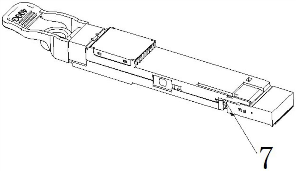
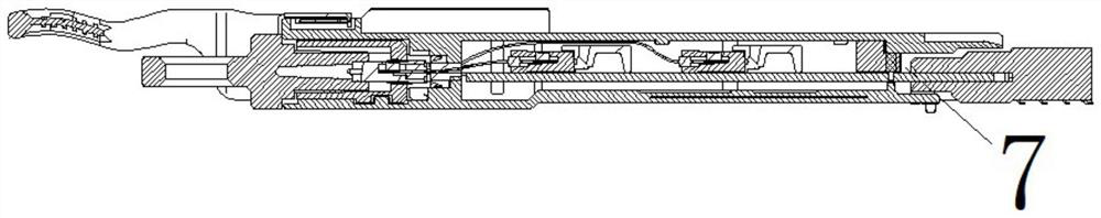
[0026] see Figure 1-2 In the prior art, when the optical module is connected to the connector, there is a large gap, which will leak the electromagnetic wave emitted by the optical module, and at the same time, the exposed metal contact of the connector will also leak the electromagnetic wave emitted by the optical module. .

[0027] see Figure 3-5 , an embodiment of the present invention provides a shielding structure for connecting the gold finger end of...


PUM


Abstract

The invention provides a shielding structure for connecting a golden finger end of an optical module, and the structure comprises a connector body, a shielding cover and a soft conductive material; the connector body is provided with an interface end connected with the optical module, and the soft conductive material is arranged on the interface end and can guide the optical module to be inserted into the connector body; the shielding cover is arranged at the upper end of the connector body in a buckled and matched mode so as to eliminate radiation leakage at the end of the connector body. The invention further provides a shielding mode for connecting the golden finger end of the optical module, and leakage radiation of the optical module can be greatly eliminated. The optical module can be directly used for replacing an existing connector component, a better shielding effect is achieved, EMI data of the optical module is reduced, the performance index and reliability of the whole system are improved, and the operation experience of a user is improved; in addition, the EMI design requirement for the optical module can be lowered, the cost of the optical module is lowered, and more exertion space can be achieved when a machine shell is designed.

Description

technical field [0001] The invention belongs to the technical field of optical modules, and in particular relates to a shielding structure and a shielding method for connecting golden finger terminals of an optical module. Background technique [0002] Connectors are mainly used to connect optical modules and circuits to transmit current or signals. In the field of optical communication, there are a large number of hot-swappable optical module development agreements (MSA), including SFP / SFP28 / DSFP / QSFP / QSFP+ / QSFP28 / QSFP-DD / OSFP / XFP / CFP / CFP2 / CFP4 / CFP8 / CXP / CDFP / SNAP12, etc. In the future, MSA upgrades will still use the hot-swappable module method. In order to facilitate the replacement of hot-swappable optical modules, there are cages and connectors of corresponding specifications on the single board of the customer equipment for optical module connection. Shield the radiation generated by the optical module. The current connectors are all installed inside the cage. When ...

Claims


Application Information

Patent Timeline
Patent Type & Authority Applications(China)
IPC IPC(8): H01R13/6581H01R13/6584H01R13/533H01R24/00
CPCH01R13/6581H01R13/6584H01R13/533
Inventor 刘寅龙王亦凡
Owner 武汉英飞光创科技有限公司
Why Eureka
Try Eureka