Rolling element having integrated electronics for use in rolling bearing

A technology of rolling bearings and rolling elements, applied in rolling contact bearings, bearing components, bearings in rotating motion, etc., can solve problems such as shortened service life and disadvantageous circuit boards, and achieve time and cost saving, easy implementation, and stress reduction. Effect

Active Publication Date: 2021-06-29
THYSSENKRUPP ROTHE ERDE GMBH +1
View PDF5 Cites 0 Cited by
  • Summary
  • Abstract
  • Description
  • Claims
  • Application Information

AI Technical Summary

Problems solved by technology

[0003] However, fixing the board directly to the hole wall proved to be disadvantageous
The deformation of the rolling elements is transferred to the circuit board, which leads to a greatly shortened service life

Method used


Image

  • Rolling element having integrated electronics for use in rolling bearing
  • Rolling element having integrated electronics for use in rolling bearing
  • Rolling element having integrated electronics for use in rolling bearing

Examples


Embodiment Construction

[0038] In the individual figures, identical components are always provided with the same reference symbols and are therefore usually also named or mentioned only once in each case.

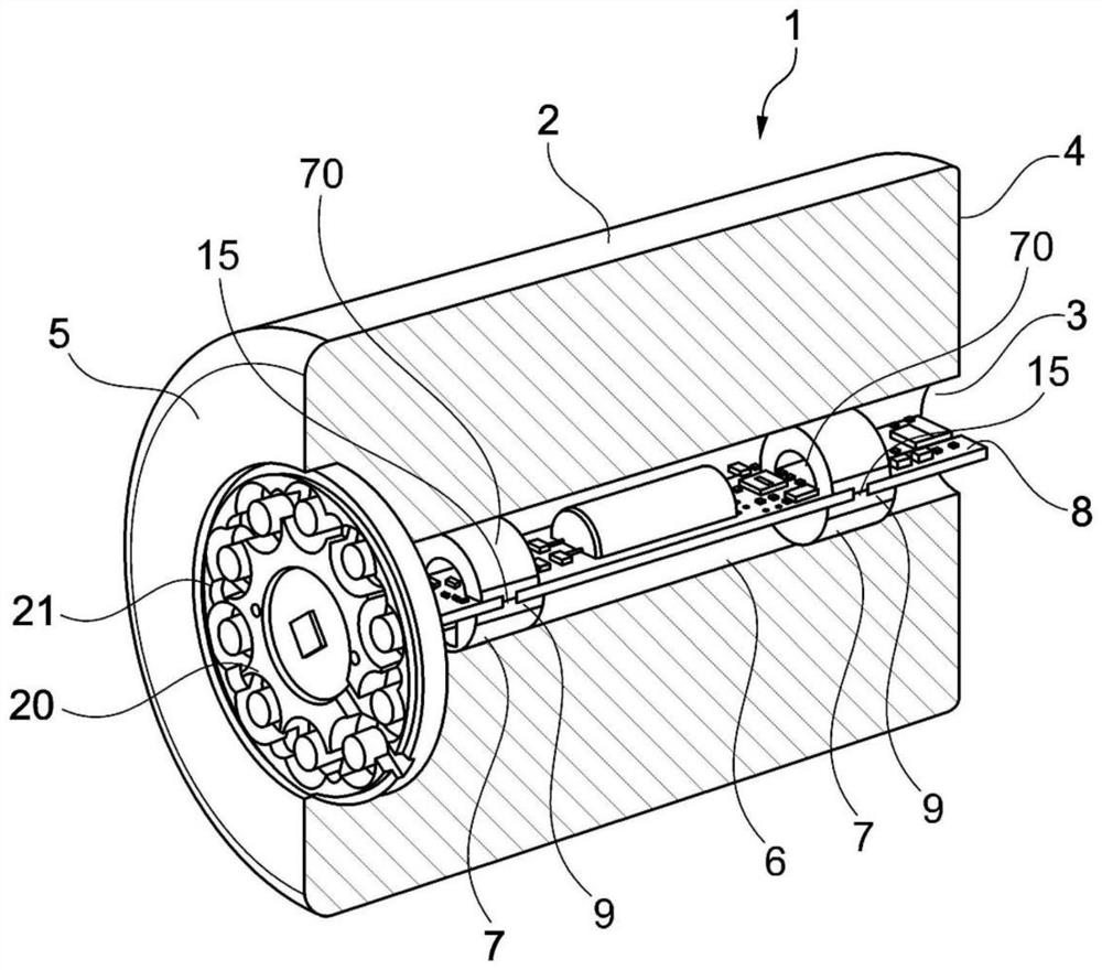
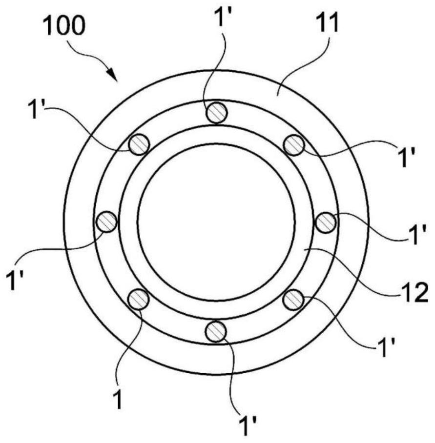
[0039] figure 1 A schematic view of a rolling body 1 according to an exemplary embodiment of the invention is shown. Such a rolling body 1 is mounted in a rolling bearing and serves for the movable guidance of the first bearing ring 11 and the second bearing ring 12 to one another, in particular for the movable guiding of the inner ring 12 arranged in the outer ring 11 of the anti-rotation arrangement. Movement guidance (see image 3 ). In this case, usually a plurality of rolling bodies are arranged between the outer ring 11 and the inner ring 12 and roll on the running surfaces of the outer ring 11 and the inner ring 12 .

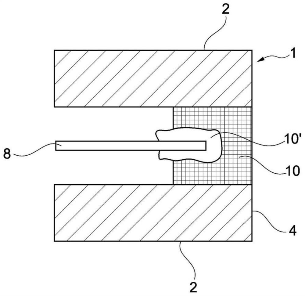
[0040] The rolling element 1 here comprises a cylindrical or substantially conical body with an outer sleeve 2 serving as a running surface on which an outer ring 11 and a...


PUM


Abstract

The invention relates to a rolling element (1), for use in a rolling bearing (100), having an outer casing (2), a first end face (4), a second end face (5) and a bore (3), wherein the bore (3) is provided along a center axis of the rolling element (1), the rolling element (1) having a PCB (8) arranged substantially parallel to the center axis of the rolling element (1) in the bore (3), the bore (3) being sealed on the first end face (4) by a closure (10), characterized in that the PCB (8) is fixed in place by the closure (10). The invention furthermore relates to a rolling bearing (100) and a method for producing a rolling element (1).

Description

Background technique [0001] In large rolling bearings, which are used, for example, in wind power plants, enormous forces act during operation. The interaction of these forces is very complex and has a considerable influence on the service life of rolling bearings. It is therefore desirable to be able to introduce electronics into the rolling elements in order to be able to perform load measurements, for example. [0002] In a large number of electronic circuits, it is usually arranged on a circuit board. In order to measure, for example, the deformation of the rolling elements caused by the load on the rolling elements, it is proposed to arrange a circuit board with suitable measuring technology inside the rolling elements. For this purpose, holes can be introduced through the rolling bodies, in which the circuit board can be arranged. [0003] However, fixing the circuit board directly to the wall of the hole proved to be disadvantageous. The deformation of the rolling e...

Claims


Application Information

Patent Timeline
Patent Type & Authority Applications(China)
IPC IPC(8): F16C19/52F16C33/34F16C41/00
CPCF16C19/522F16C33/34F16C41/00F16C2233/00F16C2360/31F16C2300/14F16C2226/18
Inventor 贡特尔·埃尔费特贝恩德·吕内堡约尔格·罗尔曼曼弗雷德·雷曼
Owner THYSSENKRUPP ROTHE ERDE GMBH
Why Eureka
Try Eureka