


Quick Research
Generate reliable direction feasibility study reports for your R&D in just a few steps.

Technical Q&A
Discover and master advanced knowledge NOW. Basics, ideas, possibilities, all at once.

Find Solutions
As an expert in R&D theories, this can generate solutions to your technical problems instantly.

Evaluate Feasibility
Analyze your overall solution with one click, know your potential R&D risks in advance.

Monitor Landscape
Get weekly tech updates, stay abreast of the latest tech innovations and key insights.
DD-PS strong anti-offset loose coupling transformer and parameter determination method thereof
A loosely coupled transformer, DD-PS technology, applied in fixed transformers or mutual inductance, transformer/inductor cores, transformer/inductor components, etc., can solve problems such as low system efficiency and weak anti-offset ability of compensation topology , to achieve the effects of reduced design difficulty, improved anti-offset performance, and excellent anti-offset performance
- Summary
- Abstract
- Description
- Claims
- Application Information
AI Technical Summary
Problems solved by technology
Method used
Image

Examples
specific Embodiment approach 1
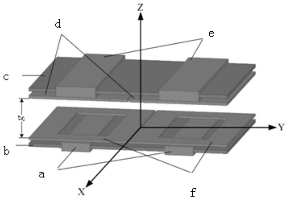
[0060] Specific implementation mode one: the following combination figure 1 Describe this embodiment, a DD-PS strong anti-offset loosely coupled transformer described in this embodiment includes a primary side coupling mechanism and a secondary side coupling mechanism; the primary side coupling mechanism and the secondary side coupling mechanism are relatively arranged;
[0061] The primary side coupling mechanism includes a primary side planar solenoid coil a, a primary side DD coil f and a primary side ferrite core b;
[0062] The primary side ferrite core b is rectangular, and the primary side DD coil f is set on the side of the primary side ferrite core b adjacent to the secondary side coupling mechanism, parallel to the primary side ferrite core b;
[0063] The primary side planar solenoid coil a is divided into two parts and wound on the primary side ferrite core b, and the number of turns of the two parts of the primary side planar solenoid coil a is the same;
[0064]...
specific Embodiment
[0119] Step 1: Determine the value range of the mutual inductance of the DD-PS loosely coupled transformer according to constraints such as voltage stress, current stress, voltage gain, and output power, and obtain the minimum mutual inductance M 12_min and the maximum mutual inductance M 12_max ;
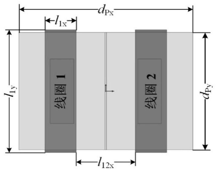
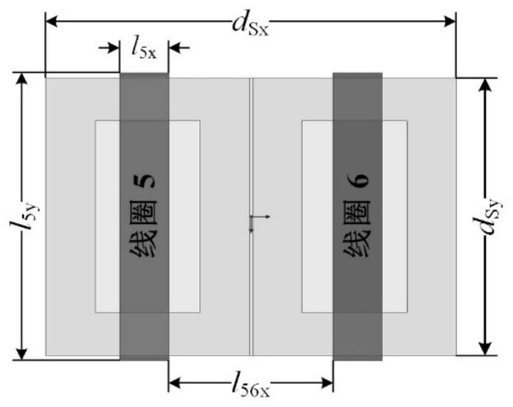
[0120] The two parts of the primary plane solenoid coil a are set as coil 1 and coil 2 respectively, the two parts of the primary side DD coil f are respectively set as coil 3 and coil 4, and the two parts of the secondary plane solenoid coil e are respectively set as Coil 5 and Coil 6, and the two parts of the secondary side DD Coil d are respectively set as Coil 7 and Coil 8; as Figures 2 to 5 shown;
[0121] Step 2: Determine the size of the primary side magnetic core and secondary side magnetic core of the loosely coupled transformer and the outer contour size of the DD coil according to the size limitation of the actual application. In order to make full use of the space a...
PUM
 Abstract
Description
Claims
Application Information
 - R&D Engineer
- R&D Manager
- IP Professional
- Industry Leading Data Capabilities
- Powerful AI technology
- Patent DNA Extraction
Browse by: Latest US Patents, China's latest patents, Technical Efficacy Thesaurus, Application Domain, Technology Topic, Popular Technical Reports.
© 2024 PatSnap. All rights reserved.Legal|Privacy policy|Modern Slavery Act Transparency Statement|Sitemap|About US| Contact US: help@patsnap.com