
Shared iron tower communication equipment installation position selection method meeting lightning protection performance

A technology for communication equipment and installation location, which is applied in the field of selection of installation locations for shared iron tower communication equipment, can solve problems such as systemicity, versatility and practicability, affecting the physical and mental health of maintenance personnel, and the performance of communication equipment cannot be guaranteed. Achieve the effects of saving design resources and time costs, protecting physical and mental health, and having a wide range of applications

Active Publication Date: 2021-06-29
NORTH CHINA POWER ENG
View PDF2 Cites 0 Cited by
  • Summary
  • Abstract
  • Description
  • Claims
  • Application Information

AI Technical Summary

Problems solved by technology

[0004] At present, the existing communication equipment installation location selection method on the shared platform mainly follows the respective regulations and relevant regulations of the two industries of electric power and communication. There is no overall requirement for the electrical distance and lightning protection requirements of communication equipment and transmission lines, systematic, Versatility and usability are not strong
Previous methods may result in unguaranteed performance of communication equipment, waste of tower resources, or affect the physical and mental health of maintenance personnel

Method used


Image

  • Shared iron tower communication equipment installation position selection method meeting lightning protection performance
  • Shared iron tower communication equipment installation position selection method meeting lightning protection performance
  • Shared iron tower communication equipment installation position selection method meeting lightning protection performance

Examples


Embodiment Construction

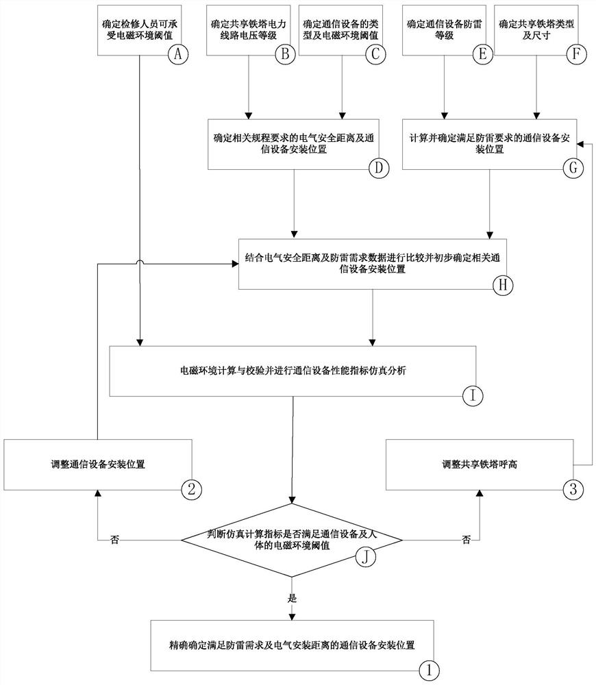
[0081] For the process steps of the method main body of the present invention, please refer to figure 1 Shown:

[0082] Step A: Determine the electromagnetic environment threshold that maintenance personnel can withstand.

[0083] Step B: Determine the voltage level of the shared iron tower power line.

[0084] Step C: Determine the type of communication equipment and its withstand electromagnetic environment threshold.

[0085] Step D: According to the relevant regulations of the electric power industry and the communication industry, as well as the project data of steps B and C, determine the electrical safety distance required by the relevant regulations and the installation position of the communication equipment on the shared iron tower.

[0086] Step E: Determine the lightning protection level of the communication equipment.

[0087] Step F: Determine the type and size of the shared iron tower.

[0088] Step G: According to the requirements of lightning protection re...


PUM


Abstract

The invention relates to a shared iron tower communication equipment installation position selection method meeting the lightning protection performance, and provides a communication equipment installation position design method by using computer equipment and programs to participate in operation, referring to related requirements of the communication industry and simultaneously performing judgment through lightning protection simplified calculation in combination with electromagnetic parameters. Electromagnetic environment indexes are obtained through electromagnetic environment simulation calculation, then communication equipment performance simulation calculation is conducted, whether the communication equipment performance indexes and the electromagnetic environment index tolerance threshold value of maintainers are met or not is verified through calculation results, and finally the optimal installation position of the communication equipment on the shared iron tower is accurately determined. And meanwhile, the requirements of lightning protection performance of communication equipment on a shared iron tower, the electrical clearance distance of a high-voltage transmission line and the like can be met, the performance of the communication equipment and the physiological and psychological health of maintenance personnel are ensured, and design resources and time cost are saved.

Description

technical field [0001] The invention relates to the field of iron tower sharing in the communication industry and the electric power industry, in particular to a method for selecting installation positions of shared iron tower communication equipment that meets lightning protection performance. Background technique [0002] Nowadays, "Sharing Tower" joins the big family of "Sharing Economy". Tower sharing in the communication industry and the power industry means that communication base stations, communication antennas and other communication equipment are hung on the power tower. "Sharing Tower" has entered the stage of comprehensive promotion. Specifically, the sharing of iron towers refers to the installation of communication equipment or other industry equipment and facilities on the power tower poles to realize the reuse and comprehensive utilization of power channel resources. At present, the application of shared iron towers is usually to install communication base st...

Claims


Application Information

Patent Timeline
Patent Type & Authority Applications(China)
IPC IPC(8): G06Q10/06G06Q10/00G06Q50/06G06Q50/30G06F30/20
CPCG06Q10/0637G06Q10/06393G06Q10/20G06Q50/06G06F30/20G06Q50/40Y04S10/50
Inventor 周辰戴雨剑王睿李晨侯聪杨世成张海建马继山柏丹丹张孜毅陈立国石岩梁立龙
Owner NORTH CHINA POWER ENG
Learn More