
Optical system for optical axis calibration and optical axis calibration method

An optical system and calibration method technology, applied in optics, optical components, instruments, etc., can solve the problems of inability to calibrate the camera module, difficult to determine specifications, and increase the difficulty of calibration.

Pending Publication Date: 2021-06-29
O FILM IMAGE TECH (GUANGZHOU) CO LTD
View PDF0 Cites 2 Cited by
  • Summary
  • Abstract
  • Description
  • Claims
  • Application Information

AI Technical Summary

Problems solved by technology

[0003] The optical axis calibration of the existing camera module is mainly calibrated through the resolution test card of the camera module, but it is often difficult to determine the specifications through the resolution test card calibration
When the specification is too strict, it will increase the difficulty of calibration; when the given specification is too loose, it is easy to cause the position deviation of the camera module, resulting in poor imaging
Moreover, the camera module often has a certain relative angle with the support, and the prior art cannot calibrate the camera module with the relative angle.

Method used


Image

  • Optical system for optical axis calibration and optical axis calibration method
  • Optical system for optical axis calibration and optical axis calibration method

Examples


Embodiment Construction

[0026] The technical solutions in the embodiments of the present invention will be clearly and completely described below in conjunction with the accompanying drawings in the embodiments of the present invention. Obviously, the described embodiments are only part of the embodiments of the present invention, not all of them. Based on the implementation manners in the present invention, all other implementation manners obtained by persons of ordinary skill in the art without making creative efforts belong to the scope of protection of the present invention.

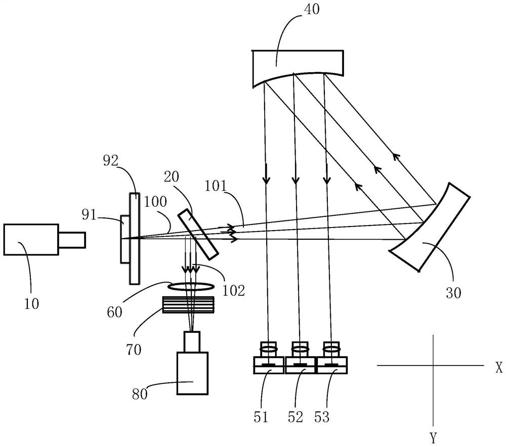
[0027] Please refer to figure 1 , the embodiment of the present invention provides an optical system for optical axis calibration, including a light source 10, a beam splitter 20, a first reflector 30, a second reflector 40 and a detection assembly (refer to figure 1 reference numerals 60, 70 and 80). The beam splitter 20 is disposed on the light emitting side of the light source 10 , and the first reflector 30 is disposed...


PUM


Abstract

The invention provides an optical system for optical axis calibration and a optical axis calibration method. The optical system comprises a light source, a spectroscope, a first reflector, a second reflector and a detection assembly, wherein the light source, the spectroscope and the first reflector are sequentially arranged on a first straight line, the light source emits light beams towards the spectroscope, the second reflector is opposite to the first reflector, the detection assembly and the spectroscope are arranged on a second straight line, and the first straight line intersects with the second straight line; the light source emits a light beam which passes through the spectroscope to form a first light beam, and the first light beam is reflected by the spectroscope to form a second light beam; the first light beam is reflected by the first reflecting mirror and the second reflecting mirror in sequence to enter the camera module; the second light beam enters the detection assembly, and the first light beam and the second light beam have a uniquely determined corresponding relation; and the optical system is adjusted to enable the angle of the first light beam to meet the calibration requirement, and the optical axis of the camera module is set to coincide with the first light beam to realize optical axis calibration of the camera module.

Description

technical field [0001] The invention belongs to the technical field of structure correction of camera modules, and in particular relates to an optical system for optical axis calibration and an optical axis calibration method. Background technique [0002] When the camera module is installed on the bracket, it is necessary to adjust the relative positional relationship between the camera module and the bracket, mainly the optical axis calibration (active alignment, AA) of the camera module, so that when the bracket is installed on the mobile terminal, the camera The module can match the structure of the mobile terminal, and make the mobile terminal have better image quality. [0003] The optical axis calibration of the existing camera module is mainly calibrated through the resolution test card of the camera module, and it is often difficult to determine the specification through the resolution test card calibration. When the specification is too strict, it will increase th...

Claims


Application Information

Patent Timeline
Patent Type & Authority Applications(China)
IPC IPC(8): G02B27/62
CPCG02B27/62
Inventor 胡伟鹏
Owner O FILM IMAGE TECH (GUANGZHOU) CO LTD
Learn More