Fracture trend fault displacement graphical calculation method based on fault intersection plane line

A technology of graphical calculation and intersection line, applied in measurement devices, instruments, scientific instruments, etc., can solve the problems of difficult to find the total fault distance of faults, low calculation probability, low numerical accuracy, etc., to achieve easy operation and realization, Comprehensively consider factors and calculate effects with high probability

Active Publication Date: 2021-06-29
CHINA UNIV OF MINING & TECH
View PDF9 Cites 0 Cited by
  • Summary
  • Abstract
  • Description
  • Claims
  • Application Information

AI Technical Summary

Problems solved by technology

[0004] However, the above-mentioned method in the prior art has at least the following defects: 1. Based on the above-mentioned calculation method 1, it is difficult to obtain the total fault distance of the fault, and it is very difficult to solve the actual production problem
2. Based on the above calculation method 2, it is generally assumed that the section is upright and has no rotation, and the strike-slip displacement calculation method of different rotation angles is not considered, and the numerical accuracy obtained under the rotation condition is not high
3. Based on the above calculation method 3, it is mainly applicable to active boundary faults in some strike-slip pull-apart basins, and not applicable to the calculation of strike-slip fault displacement of small structures in other structures
4. Based on the above calculation method 4 and calculation method 5, the probability of finding a special geological body with the same landmark on both sides of the fault is low, and the calculated probability is low
5. Based on the above calculation method 6, it is not easy to find the plane outcrop of the thrust double-nappe structure, and the lateral expansion of the structural deformation needs to be ignored, and the slippage of the overlying strata, the denudation situation, and the impact of the thrust component on the wall must also be considered. Influencing factors
6. Based on the above calculation method 7, seismic data and logging data cannot be well combined due to inconsistent accuracy, and identification is difficult, and the calculation probability is low

Method used


Image

  • Fracture trend fault displacement graphical calculation method based on fault intersection plane line
  • Fracture trend fault displacement graphical calculation method based on fault intersection plane line

Examples


specific Embodiment approach

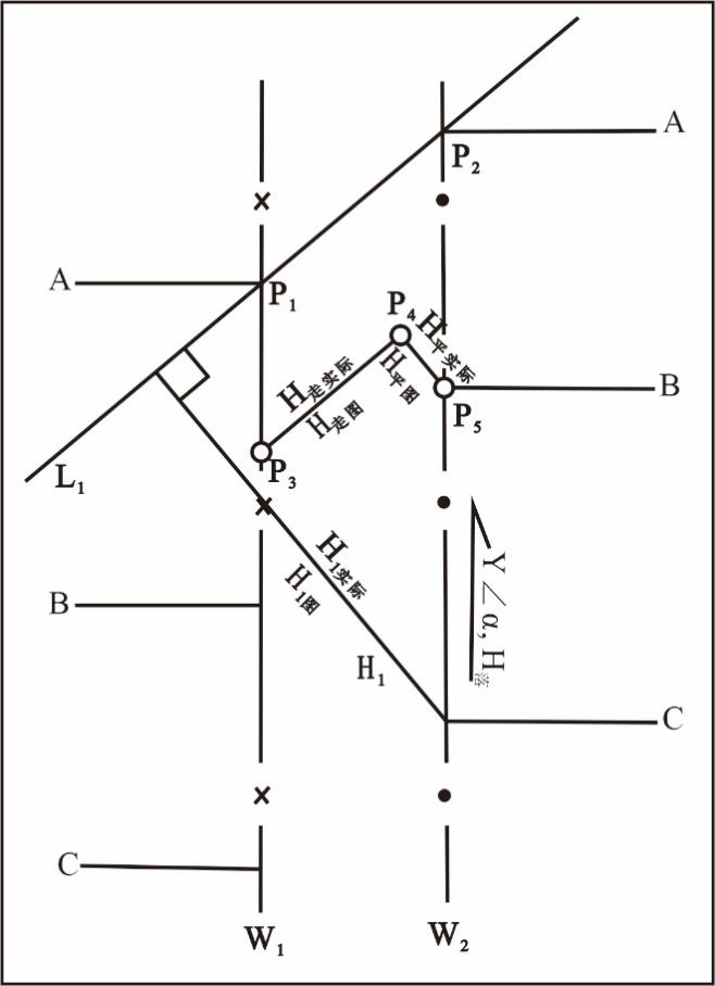
[0051] Specific implementation method: the P 4 Along the strike of the fault plane (L 1 ) towards the intersection of another fault line W 1 move until W 1 P on 3 , the line is the position of the strike and throw of the fault on the fault outline map.

[0052] Measure P by applying the method in step 5 3 and P 4 distance H on the graph 走图 , and then converted to the actual distance H according to the ratio in step 5 走实际 , which is the strike distance of the fault.

[0053] Step 8: Identify the relative migration direction of the fracture. Since the strike and throw of the fault have not only the size but also the direction, in the actual mineral production or geological calculation, according to the structural evolution background of the fault in this study area, it is found that the relative migration direction of the fault is directly upward. Arrows marking upward translation indicate the relative direction of translation of the disc.


PUM


Abstract

A fracture trend fault displacement graphical calculation method based on a fault intersection plane line comprises the following steps: drawing a fracture structure outline diagram of a typical stratum interface contour line, obtaining basic geological occurrences such as trend, inclination, inclination angle [alpha], fall H and extension length L through various methods, introducing a quantitative relationship among the geological occurrences, and through adoption of a graphical method, and by means of the proportional relation between the actual value of the geological occurrence in the actual production process and the value of the geological occurrence in the fracture outline map, obtaining the fault strike fault displacement through mutual conversion. According to the method, the mineral exploitation safety can be improved, and the mineral exploitation cost can be reduced.

Description

technical field [0001] The invention relates to the technical field of coal geological exploration, in particular to a graphical calculation method of fault strike and distance based on fault intersection lines. Background technique [0002] In the process of mineral exploration, the distance between the two ore layers of the fault after the ore layer is dislocated by a fault is an indispensable data for the development of mineral resources. The occurrence of safety accidents is of great significance. However, relevant technical personnel only pay attention to the distance of the fault along the inclined direction, that is, the drop and leveling of the fault. In fact, the fault still has a slip distance on the strike, that is, the strike distance, but the predecessors did not pay enough attention. [0003] At present, the existing methods for calculating the fault throw along the strike of the fault zone mainly include the following methods: Calculation method 1: On the bas...

Claims


Application Information

Patent Timeline
Patent Type & Authority Applications(China)
IPC IPC(8): G01V1/28G01V1/30
CPCG01V1/28G01V1/306
Inventor 屈争辉李浩郭梁朱冠宇章必成张闯李明震周元
Owner CHINA UNIV OF MINING & TECH
Why Eureka
Try Eureka