
Retainer for rolling bearing and rolling bearing

A technology of rolling bearings and cages, which is applied to bearing components, shafts, bearings, mechanical equipment, etc., can solve problems such as cage fracture, achieve the effect of ensuring support stability and reducing overall weight

Pending Publication Date: 2021-06-29
SCHAEFFLER TECH AG & CO KG
View PDF3 Cites 0 Cited by
  • Summary
  • Abstract
  • Description
  • Claims
  • Application Information

AI Technical Summary

Problems solved by technology

The cage according to the current solution, especially the nylon cage, will break the cage in some high-speed applications

Method used


Image

  • Retainer for rolling bearing and rolling bearing
  • Retainer for rolling bearing and rolling bearing
  • Retainer for rolling bearing and rolling bearing

Examples


Embodiment Construction

[0028] figure 1 A perspective partial sectional view of a rolling bearing according to a preferred embodiment is shown. Such as figure 1 As shown, the rolling bearing comprises an outer ring 2 and an inner ring 1 arranged coaxially and a row of rolling elements 3 arranged between the outer ring 2 and the inner ring 1 . The rolling bodies are here configured as balls 3 . The rolling bearing also includes a cage 4 integrally made of nylon material to isolate and guide the balls 3 .

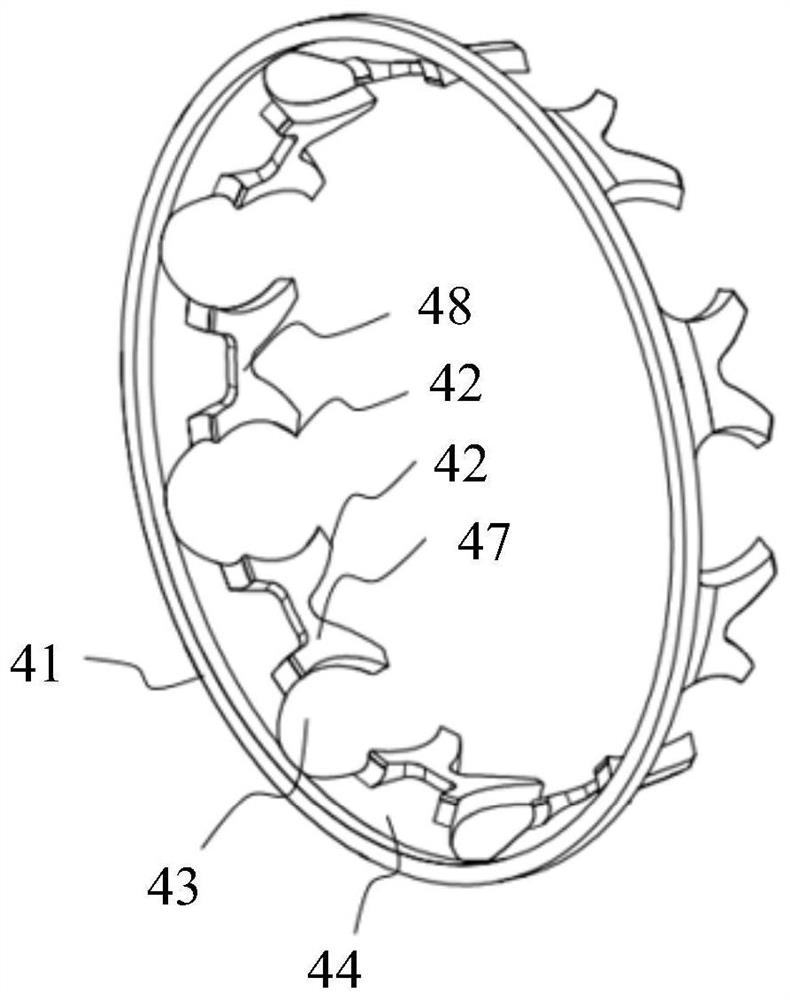
[0029] The cage 4 according to the present embodiment consists of Figure 2 to Figure 5 show.

[0030] figure 2 with image 3Perspective views of the cage viewed from different viewing angles are shown. As shown in the figure, the cage 4 has a cage ring 41 and a cage beam protruding from an axial end face of the cage ring 41, the cage beam here having a substantially flat design and extending approximately in the axial direction of the bearing . A pocket 43 for accommodating the balls 3 an...


PUM


Abstract

The invention relates to a retainer for a rolling bearing and the rolling bearing. The retainer comprises a retainer ring (41) and retainer beams projecting from at least one axial end surface of the retainer ring (41), a pocket (43) for receiving a rolling body (3) of the rolling bearing being formed between two adjacent retainer beams, each retainer beam has a support beam (44) projecting from the retainer ring (41) and a catch (42) projecting from an end of the support beam (44) at least partially towards both circumferential sides, a reinforcing rib (48) radially thickening the retainer beam being formed in a rolling element circumferential support region of the retainer beam; and the rolling bearing comprises the retainer.

Description

technical field [0001] The invention relates to the field of bearings. In particular, the invention relates to a cage for a rolling bearing and a rolling bearing comprising the cage. Background technique [0002] A conventional rolling bearing includes an outer ring and an inner ring arranged concentrically, and includes rolling elements arranged between the outer ring and the inner ring. Rolling bearings also include cages to isolate the rolling elements and to guide and hold them within the bearing. A common cage design scheme is the clip-type cage scheme, which designs one end of the cage as an open type. On the premise of providing sufficient axial limit, the cage can be installed from the axial direction, which simplifies, for example, ball bearings. The assembly process of rolling bearings. For example, US patent document US 6,416,230 B1 discloses a snap-in cage for deep groove ball bearings. As another example, Chinese patent document CN 101978181 also discloses a...

Claims


Application Information

Patent Timeline
Patent Type & Authority Applications(China)
IPC IPC(8): F16C33/38F16C33/44
CPCF16C33/3843F16C33/3856F16C33/44
Inventor 雷飞
Owner SCHAEFFLER TECH AG & CO KG
Learn More