Adjustable ceramic tile punching equipment for building materials
A kind of punching equipment and adjustable technology, applied in the direction of stone processing equipment, stone processing tools, cleaning methods and utensils, etc., can solve the problems of inconsistent punching standards, affecting work progress, and long punching time
- Summary
- Abstract
- Description
- Claims
- Application Information
AI Technical Summary
Problems solved by technology
Method used
Image
Examples
Embodiment 1
[0068] An adjustable tile punching device for building materials, such as figure 1As shown, it includes a support frame 1, a pressing mechanism 2 and a transmission mechanism 3. A pressing mechanism 2 is arranged between the front and rear sides of the upper left part of the support frame 1, and a transmission mechanism 3 is provided on the left side of the support frame 1.
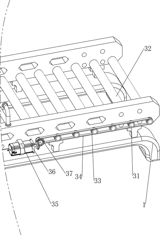
[0069] When people need to punch tiles, they can use this adjustable tile punching equipment for building materials. First, people need to put the tiles on the conveying mechanism 3 and be located under the pressing mechanism 2, and then start the pressing mechanism 2. When the pressing mechanism 2 moves downward, the tiles can be punched. When the pressing mechanism 2 moves upward and resets, people can close the pressing mechanism 2. After the punching is completed, people start the transmission mechanism 3 again, and the transmission mechanism 3 can run. The perforated tiles are transmitted, and after ...
Embodiment 2
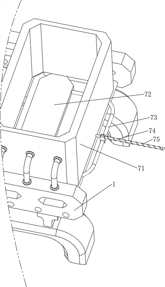
[0071] On the basis of Example 1, such as figure 2 and image 3 As shown, the pressing mechanism 2 includes a first fixed block 21, a cylinder 22, a first fixed column 23, a first spring 24, a first pressing plate 25, a slider 26, an electric drill 27, a block 28, and a second fixed column 29. And the second spring 210, the left part rear side on the support frame 1 is provided with the first fixed block 21, the cylinder 22 is installed on the first fixed block 21, the first fixed column 23 is all provided with on the left part front and rear sides of the support frame 1 The two first fixed columns 23 are slidably provided with a first pressure plate 25, and the telescopic rod of the cylinder 22 is fixedly connected with the first pressure plate 25. The two first fixed columns 23 are all wound with a first spring 24, the first The two ends of the spring 24 are respectively connected with the first pressing plate 25 and the support frame 1, the middle of the first pressing pl...
Embodiment 3
[0076] On the basis of Example 2, such as Figure 4-Figure 7 Shown, also include hold-down mechanism 4, hold-down mechanism 4 includes the 3rd fixed post 41, the 3rd spring 42, the 2nd press plate 43, press post 44, the 4th spring 45, left front and rear two on the support frame 1 Two third fixed columns 41 are arranged at intervals on the sides, and a second pressure plate 43 is slidably arranged between the tops of the four third fixed columns 41. The second pressure plate 43 cooperates with the first pressure plate 25, and the four third fixed columns 41 The third spring 42 is wound on the top, and the two ends of the third spring 42 are connected with the second pressure plate 43 and the support frame 1 respectively. There is a fourth spring 45, and the two ends of the fourth spring 45 are respectively connected with the second pressing plate 43 and the pressing post 44.
[0077] When the first pressing plate 25 moves downward, the first pressing plate 25 makes the second...
PUM
 Abstract
Description
Claims
Application Information
 - Generate Ideas
- Intellectual Property
- Life Sciences
- Materials
- Tech Scout
- Unparalleled Data Quality
- Higher Quality Content
- 60% Fewer Hallucinations
Browse by: Latest US Patents, China's latest patents, Technical Efficacy Thesaurus, Application Domain, Technology Topic, Popular Technical Reports.
© 2025 PatSnap. All rights reserved.Legal|Privacy policy|Modern Slavery Act Transparency Statement|Sitemap|About US| Contact US: help@patsnap.com


