A manipulator device for power equipment maintenance

A technology for power equipment and manipulators, which is applied to manipulators, transmission devices, switch devices, etc., can solve the problems of inability to clamp and fix test clips, unfavorable test clips sent to high places to clamp power equipment, and inability to adapt to the use of test clips.

Inactive Publication Date: 2021-09-14
PINGLIANG POWER SUPPLY CO STATE GRID GANSU ELECTRIC POWER CO LTD
View PDF0 Cites 2 Cited by
  • Summary
  • Abstract
  • Description
  • Claims
  • Application Information

AI Technical Summary

Problems solved by technology

[0003] The existing operation method generally needs to be completed with the help of a manipulator device, but the existing device cannot reliably clamp and fix the test clip, which is not conducive to stably sending the test clip to a high place and clamping the electrical equipment, and cannot adapt to different The use of test clips for working conditions and models has large application limitations

Method used


Image

  • A manipulator device for power equipment maintenance
  • A manipulator device for power equipment maintenance
  • A manipulator device for power equipment maintenance

Examples


Embodiment 1

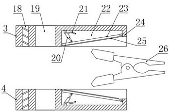
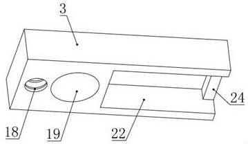
[0024] see Figure 1-4 , in an embodiment of the present invention, a manipulator device for power equipment maintenance includes an insulating rod 8, the upper part of the insulating rod 8 is provided with an upper splint 3 and a lower splint 4 for sliding, and the upper splint 3 and the lower splint 4 are vertical Arranged directly opposite to each other, a set of pneumatic adjustment splint assemblies are respectively installed on the opposite side of the upper splint 3 and the lower splint 4, and a control assembly for simultaneously controlling the two sets of pneumatic adjustment splint assemblies is installed on the lower part of the insulating rod 8. The side of the upper splint 3 and the lower splint 4 away from the pneumatic adjustment splint assembly is threadedly connected with a positive and negative threaded rod 2, and the upper end of the insulating rod 8 is equipped with an upper support plate 1 and a lower splint that is rotatably connected to the upper end of ...

Embodiment 2

[0027] see Figure 1-4 , the difference between this embodiment and embodiment 1 is:

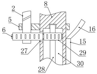
[0028] In this embodiment, the upper splint 3 and the lower splint 4 are provided with a sliding hole 19 that is slidably connected with the insulating rod 8, and the upper splint 3 and the lower splint 4 are also provided with a threaded connection with the positive and negative threaded rod 2. Threaded hole 18; the transmission assembly includes an external transmission gear 6, a rotating ring 9, an insulating rotating rod 28 and an internal transmission gear 29, and the lower end of the positive and negative threaded rod 2 is fixed with an external transmission gear 6, and the external transmission gear 6 It is meshed with the internal transmission gear 29 provided in the insulating rod 8. A cavity 30 is provided in the insulating rod 8. The internal transmission gear 29 is located on the top of the cavity 30. The side wall of the insulating rod 8 is also provided with an external transmi...


PUM


Abstract

The invention relates to the field of power equipment maintenance, in particular to a manipulator device for power equipment maintenance, including an insulating rod, the upper part of the insulating rod is provided with an upper splint and a lower splint for sliding cooperation, and the opposite side of the upper splint and the lower splint A set of pneumatic adjustment splint assemblies are respectively installed inside, and a control assembly for simultaneous control of the two sets of pneumatic adjustment splint assemblies is installed on the lower part of the insulating rod. The side of the upper splint and the lower splint away from the pneumatic adjustment splint assembly is connected with a screw thread. The positive and negative threaded rods are also mounted on the insulating rods for driving the rotation of the positive and negative threaded rods. The invention can reliably clamp and fix the test clip, is beneficial to stably sending the test clip to a high place and clamping the electric equipment, and can adapt to the use of test clips of different working conditions and types, and is worthy of popularization.

Description

technical field [0001] The invention relates to the field of power equipment maintenance, in particular to a manipulator device for power equipment maintenance. Background technique [0002] In the daily operation of power equipment, one of the important daily tasks of maintenance personnel is to inspect and test various power components such as transformers involved in power equipment. This work involves a frequent step: installing the test clip to the power equipment designated position and remove the test clip after the test is complete. [0003] The existing operation method generally needs to be completed with the help of a manipulator device, but the existing device cannot reliably clamp and fix the test clip, which is not conducive to stably sending the test clip to a high place and clamping the electrical equipment, and cannot adapt to different The use of test clips with different working conditions and models has great application limitations. Therefore, in view ...

Claims


Application Information

Patent Timeline
Patent Type & Authority Patents(China)
IPC IPC(8): B25J11/00F16H37/12H02B3/00
CPCB25J11/00F16H37/12H02B3/00
Inventor 孙沛张小勇高小明韦宗辰
Owner PINGLIANG POWER SUPPLY CO STATE GRID GANSU ELECTRIC POWER CO LTD
Why Eureka
Try Eureka