
CT (computerized tomography computed tomography) detection system of asymmetric FOV (field of view)

A detection system and asymmetric technology, applied in the field of CT detection system with asymmetric FOV, can solve problems such as asymmetric FOV

Inactive Publication Date: 2021-06-29
上海璋尺铎柃企业管理有限公司
View PDF0 Cites 0 Cited by
  • Summary
  • Abstract
  • Description
  • Claims
  • Application Information

AI Technical Summary

Problems solved by technology

[0005] How to use the same set of rack equipment to meet the CT detection of the two situations of FOV of 40 and FOV of 50 has become an urgent technical problem to be solved. At present, there is no technical solution that can solve the above technical problems. ground, there is no CT detection system with an asymmetric FOV

Method used


Image

  • CT (computerized tomography computed tomography) detection system of asymmetric FOV (field of view)
  • CT (computerized tomography computed tomography) detection system of asymmetric FOV (field of view)
  • CT (computerized tomography computed tomography) detection system of asymmetric FOV (field of view)

Examples


Embodiment Construction

[0022] In order to better clearly express the technical solution of the present invention, the present invention will be further described below in conjunction with the accompanying drawings.

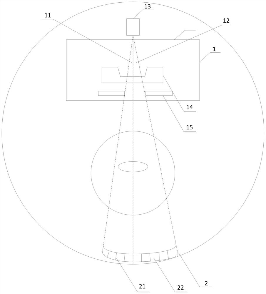
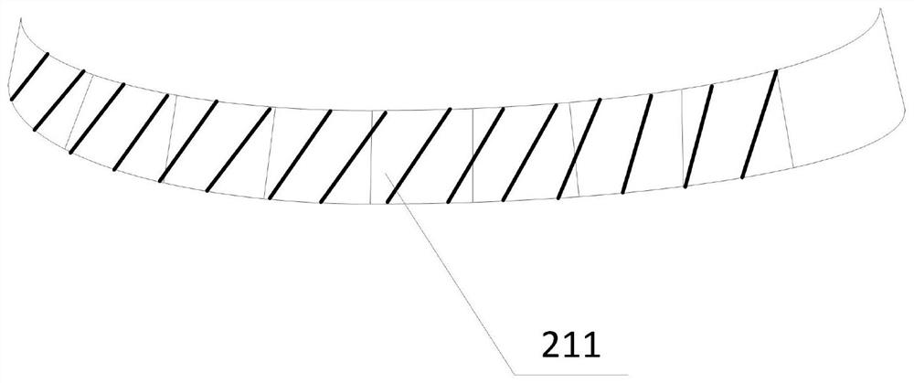
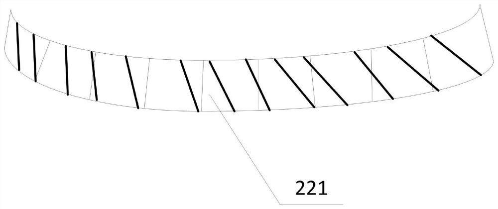
[0023] figure 1 It shows a specific embodiment of the present invention, a schematic structural diagram of a CT detection system with an asymmetric FOV. Those skilled in the art understand that the present invention aims to significantly improve the working principle and mechanical structure involved in this application. Describe in detail, so in this application Figure 1 to Figure 3 Some unimportant structures and components are not marked or displayed in the document, such as screws, shafts, casings, etc., but this does not mean that there are no such components in actual use and operation. Under the premise of having the technical means described in this application , all technical solutions formed by combining CT systems of the prior art are technical solutions that need to be pro...


PUM


Abstract

The invention provides a CT (computerized tomography computed tomography) detection system of asymmetric FOV (field of view). The system at least comprises a high-voltage ray generating device (1) and a ray receiving detector (2), the high-voltage ray generating device (1) is arranged to meet a first emitting angle (11) of a first FOV and a second emitting angle (12) of a second FOV, the ray receiving detector (2) is arranged to be in an asymmetric layout. The ray receiving detector (2) is divided into a first detection part (21) and a second detection part (22) by taking the central axis of the high-voltage ray generating device (1) as a boundary, and the length of the first detection part (21) is smaller than that of the second detection part (22). The system is simple in structure and powerful in function, reduces the production cost compared with the prior art, is safe and convenient, and has extremely high commercial value.

Description

technical field [0001] The invention belongs to the technical field of CT radiography, in particular to an asymmetrical FOV CT detection system. Background technique [0002] In CT equipment, after X-rays are emitted from the X-ray tube, they need to be collimated by a collimator before they are irradiated to the object to be inspected and then received by the detector. The main function of the collimator is to confine the X-rays to a fan beam in the Z direction and the Ψ plane, and to shield the X-rays in other directions. Field of view: Abbreviation for field of view, FOV for short. [0003] At present, in the existing imaging fields, such as CT and DR collimators, the FOV is generally fixed and cannot be changed. In the Asian market, due to the small cross-section of the human chest cavity, a general FOV of 40 cm can meet the needs of general testing, while in the European and American markets, due to the large cross-section of the human chest cavity, it usually require...

Claims


Application Information

Patent Timeline
Patent Type & Authority Applications(China)
IPC IPC(8): A61B6/03
CPCA61B6/035A61B6/4064A61B6/44
Inventor 吴迎瓞
Owner 上海璋尺铎柃企业管理有限公司
Learn More