
Display module

A technology of display modules and display screens, which is applied to TVs, color TV parts, electrical components, etc., which can solve problems such as poor shooting effects and achieve good imaging effects

Pending Publication Date: 2021-06-25
HEFEI VISIONOX TECH CO LTD
View PDF6 Cites 0 Cited by
  • Summary
  • Abstract
  • Description
  • Claims
  • Application Information

AI Technical Summary

Problems solved by technology

[0003] An embodiment of the present invention provides a display module to solve the problem that the front camera of the existing display device has poor shooting effect in an environment with low brightness

Method used


Image

  • Display module
  • Display module
  • Display module

Examples


Embodiment Construction

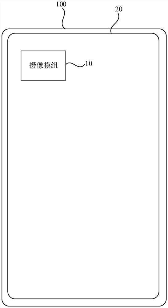
[0043] The present invention will be further described in detail below in conjunction with the accompanying drawings and embodiments. It should be understood that the specific embodiments described here are only used to explain the present invention, but not to limit the present invention. In addition, it should be noted that, for the convenience of description, only some structures related to the present invention are shown in the drawings but not all structures.

[0044] As mentioned in the background technology, the front-facing camera of the existing display device generally uses the screen to fill light or use an algorithm to compensate in a low-brightness environment. There are insufficient Selfie brightness in a dark environment, which leads to poor shooting effects such as photo distortion. good question.

[0045] Based on the above technical problems, this embodiment proposes the following solutions:

[0046] figure 1 It is a schematic structural diagram of a displa...


PUM


Abstract

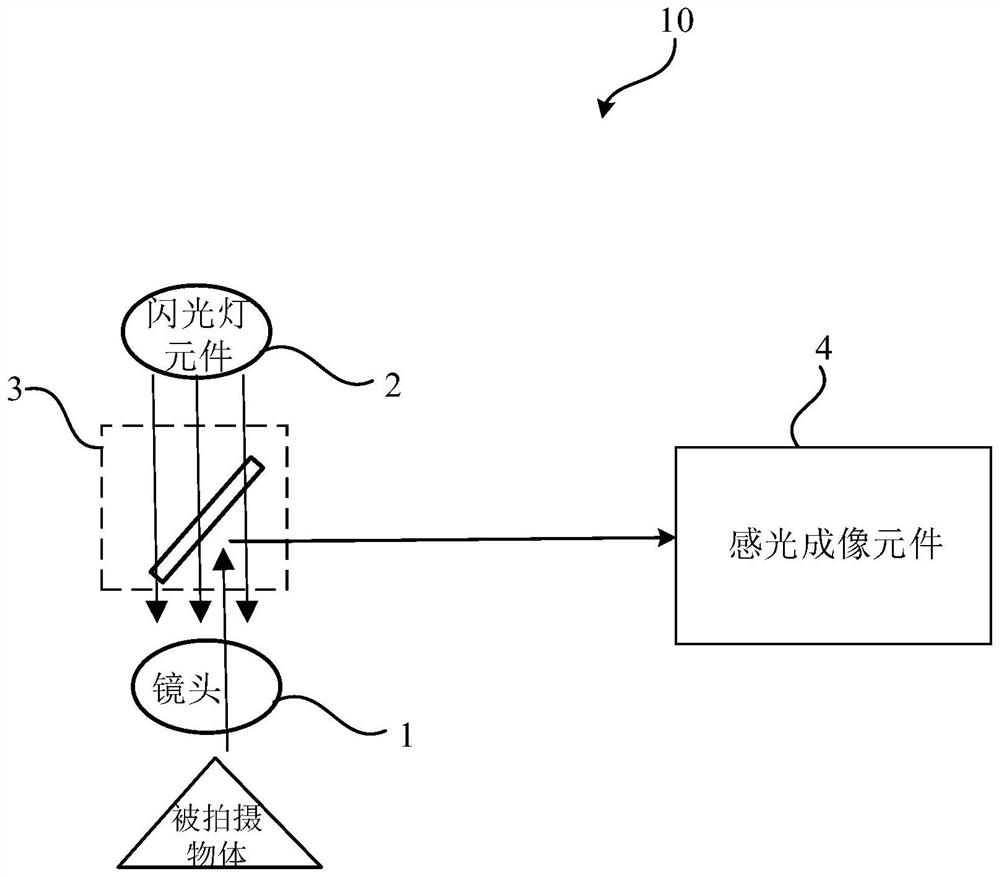
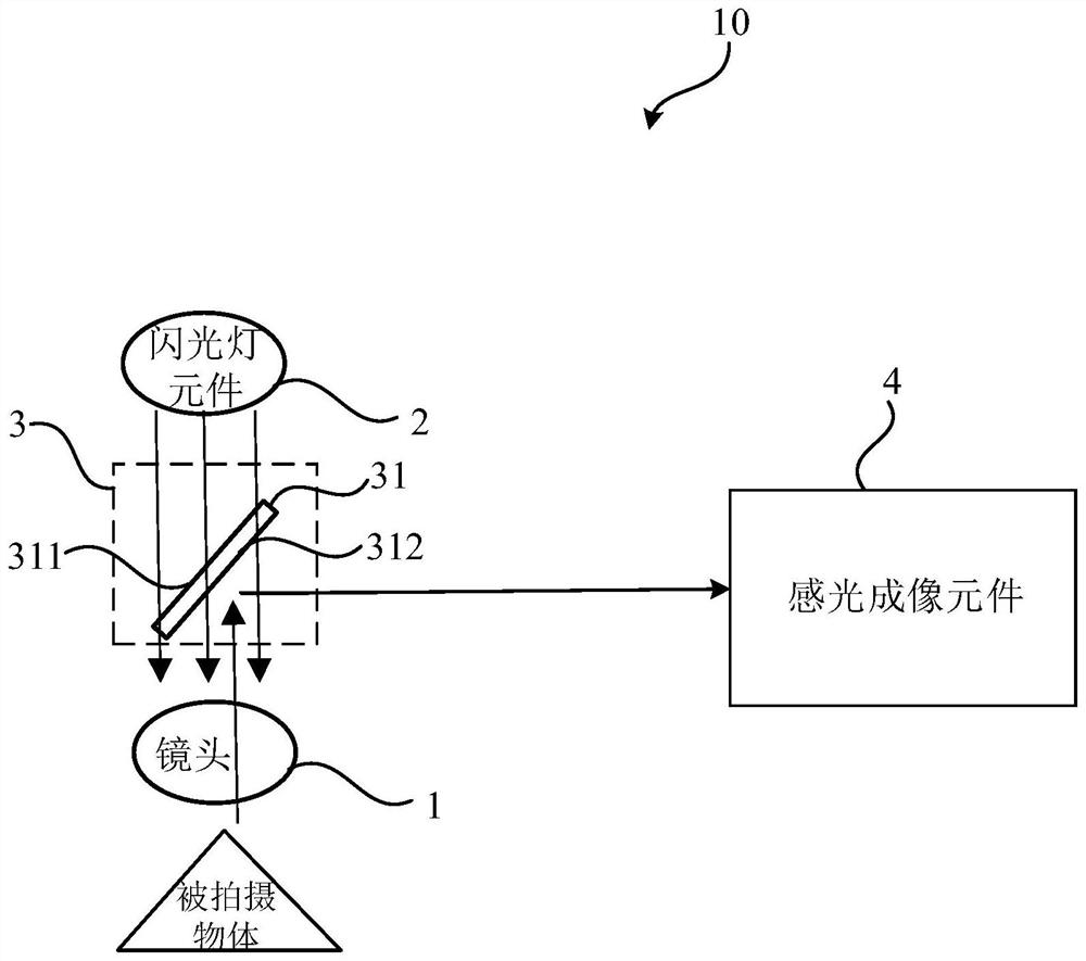
The embodiment of the invention discloses a display module. A camera shooting module of the display module comprises a lens, a flash lamp element, a light path adjusting unit and a photosensitive imaging element, the lens is used for amplifying a shot object, the flash lamp element and the lens are located on the same straight line, the flash lamp element is used for supplementing light, and the light path adjusting unit is at least arranged between the flash lamp element and the lens. The light path adjusting unit is used for transmitting light emitted by the flash lamp element to the lens, refracting the light to the surface of a shot object through the lens and totally reflecting the light reflected by the surface of the shot object and received by the lens, and the photosensitive imaging element is used for imaging according to the light totally reflected by the light path adjusting unit. According to the technical scheme provided by the embodiment of the invention, a light supplementing effect is achieved through the light emitted by the flash lamp element, so that the imaging effect of the photosensitive imaging element of the camera module is relatively good, and the problem that a front camera of an existing display device is poor in shooting effect in a relatively low brightness environment is solved.

Description

technical field [0001] Embodiments of the present invention relate to the field of display technology, and in particular, to a display module. Background technique [0002] With the development of display technology and the improvement of people's living standards, users have higher and higher requirements for the pixels of the display device. The rear camera of the display device relies on ultra-high pixels and excellent algorithms, and the picture quality is better, while the existing The front camera of the display device has the problem of poor shooting effect in a low-brightness environment. Contents of the invention [0003] An embodiment of the present invention provides a display module to solve the problem that the front camera of the existing display device has poor shooting effect in an environment with low brightness. [0004] In order to achieve the above technical problems, the present invention adopts the following technical solutions: [0005] An embodime...

Claims


Application Information

Patent Timeline
Patent Type & Authority Applications(China)
IPC IPC(8): H04N5/225
CPCH04N23/57H04N23/56H04N23/55H04N23/54
Inventor 施嘉懿张明
Owner HEFEI VISIONOX TECH CO LTD
Learn More