
Successive approximation adc and its asynchronous logic control circuit

A successive approximation type, control circuit technology, applied in electrical components, electrical signal transmission systems, instruments, etc., can solve the problem of long conversion time, and achieve the effect of short settling time, sufficient settling, and shortening the conversion time.

Active Publication Date: 2021-07-30
MICROTERA SEMICON (GUANGZHOU) CO LTD
View PDF5 Cites 0 Cited by
  • Summary
  • Abstract
  • Description
  • Claims
  • Application Information

AI Technical Summary

Problems solved by technology

[0005] In view of the shortcomings of the prior art described above, the purpose of the present invention is to provide a successive approximation ADC and its asynchronous logic control circuit, which is used to solve the problem of long conversion time in the prior art

Method used


Image

  • Successive approximation adc and its asynchronous logic control circuit
  • Successive approximation adc and its asynchronous logic control circuit

Examples


Embodiment 1

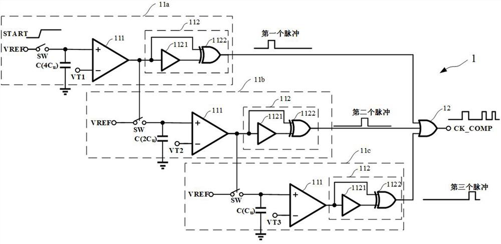
[0044] Such as figure 1 As shown, this embodiment provides an asynchronous logic control circuit 1 applied to a successive approximation ADC, and the asynchronous logic control circuit 1 includes:

[0045] The n-stage capacitor voltage tracking module and the logic module 12, wherein, n is a natural number greater than or equal to 2.

[0046] Such as figure 1 As shown, the capacitor voltage tracking modules at all levels track the voltage establishment of each weight bit capacitor in the digital-to-analog conversion module of the successive approximation ADC respectively, and generate corresponding control signals after the voltage on each capacitor is established, and based on The control signal outputs a corresponding pulse signal; the capacitor voltage tracking modules at all levels are connected sequentially, the higher the weight of the capacitor corresponding to the capacitor voltage tracking module, the higher the level, and the subsequent capacitor voltage tracking modu...

Embodiment 2

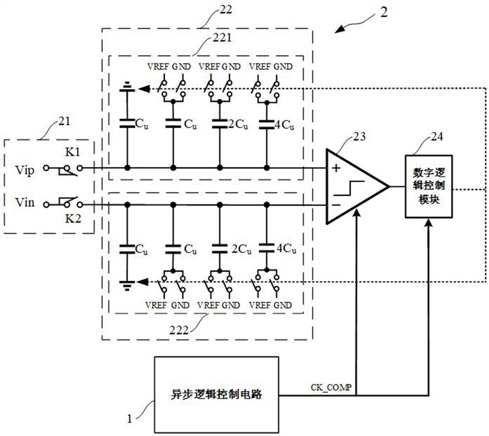
[0055] Such as figure 2 As shown, the present embodiment provides a successive approximation ADC, and the successive approximation ADC includes:

[0056] An analog-to-digital conversion circuit 2 and an asynchronous logic control circuit 1 .

[0057] Such as figure 2 As shown, the asynchronous logic control circuit 1 generates a logic control clock CK_COMP.

[0058] Specifically, the structure and working principle of the asynchronous logic control circuit 1 refer to Embodiment 1, which will not be repeated here.

[0059] Such as figure 2 As shown, the analog-to-digital conversion circuit 2 receives the logic control clock CK_COMP, and performs analog-to-digital conversion based on the logic control clock CK_COMP.

[0060] Specifically, the structure of the analog-to-digital conversion circuit 2 can be set as required, including but not limited to a single-ended structure and a differential structure. In this embodiment, the analog-to-digital conversion circuit 2 adopt...


PUM


Abstract

The present invention provides a successive approximation ADC and its asynchronous logic control circuit, including: n-level capacitor voltage tracking module, each level of capacitor voltage tracking module respectively tracks the voltage establishment of each weighted bit capacitor in the successive approximation ADC. After the completion, the corresponding control signal and pulse signal are generated; the capacitor voltage tracking modules at all levels are connected in sequence, the higher the weight of the capacitor corresponding to the capacitor voltage tracking module, the higher the level of the capacitor voltage tracking module, and the subsequent capacitor voltage tracking module receives the previous capacitor voltage tracking module The output control signal starts to work after the voltage is established by the previous capacitor voltage tracking module; the logic module is connected to the output terminals of the capacitor voltage tracking modules at all levels, and the logic control clock is triggered based on the pulse signal output by any capacitor voltage tracking module . The invention can simulate the establishment of different weight positions of the DAC, thereby accurately generating a suitable control clock and achieving the effects of saving time and improving the conversion speed of the ADC.

Description

technical field [0001] The invention relates to the field of integrated circuit design, in particular to a successive approximation ADC and its asynchronous logic control circuit. Background technique [0002] An analog-to-digital data converter (ADC) is an essential electronic component for converting natural analog signals to computer digital signals. High-speed and high-precision ADCs have always been one of the most important trends in the development of ADCs. Whether it is academic or industrial applications, people are unanimously committed to how to improve the accuracy and how to break through the speed limit. [0003] The conversion cycle of the ADC can be divided into two stages according to the chronological order of the actual work. The first stage is sampling, which accurately samples the analog signal to be converted to the capacitor and holds it; the second stage is conversion, which is to convert the first The analog signal obtained by the stage sampling is ...

Claims


Application Information

Patent Timeline
Patent Type & Authority Patents(China)
IPC IPC(8): H03M1/46
CPCH03M1/466
Inventor 刘森李建平刘兴龙刘海彬班桂春
Owner MICROTERA SEMICON (GUANGZHOU) CO LTD
Learn More