
Impact surge current positioning method

A positioning method and rush current technology, applied in the direction of measuring electricity, fault location, measuring electrical variables, etc., can solve the problems of the influence of the service life of the insulation transformer, the increase of the eddy current loss of the transformer, and the increase of the leakage flux of the transformer.

Active Publication Date: 2021-06-25
SHANGHAI MUNICIPAL ELECTRIC POWER CO +1
View PDF10 Cites 0 Cited by
  • Summary
  • Abstract
  • Description
  • Claims
  • Application Information

AI Technical Summary

Problems solved by technology

At the same time, the leakage flux of the transformer becomes larger, and the increase of reactive power loss leads to a serious drop in the voltage of the power system, and the relay protection device of the system will also appear abnormal actions
The increased leakage flux will also increase the eddy current loss of the transformer, which will seriously affect the insulation of the body and even the service life of the transformer

Method used


Image

  • Impact surge current positioning method
  • Impact surge current positioning method
  • Impact surge current positioning method

Examples


Embodiment Construction

[0029] The following will refer to the attached Figure 1 to Figure 5 Specific examples of the present invention are described in more detail. Although specific embodiments of the invention are shown in the drawings, it should be understood that the invention may be embodied in various forms and is not limited to the embodiments set forth herein. Rather, these embodiments are provided for more thorough understanding of the present invention and to fully convey the scope of the present invention to those skilled in the art.

[0030] It should be noted that certain terms are used in the specification and claims to refer to specific components. Those skilled in the art should understand that they may use different terms to refer to the same component. The specification and claims do not use differences in nouns as a way of distinguishing components, but use differences in functions of components as a criterion for distinguishing. "Includes" or "comprises" mentioned throughout ...


PUM


Abstract

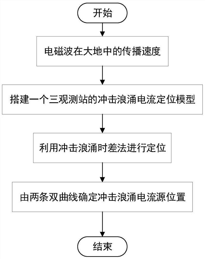
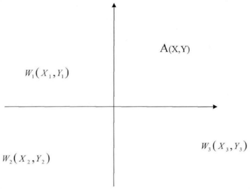
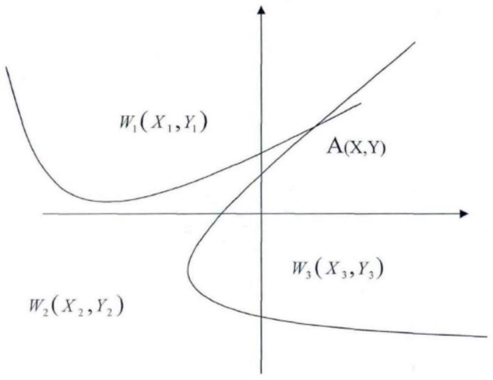
The invention discloses an impact surge current positioning method, and the method comprises the steps: determining the propagation velocity V of an electromagnetic wave in the ground; establishing at least three earth surface potential observation points, analyzing the time domain waveform of the scalar potential of the earth surface potential observation points caused by the impact current, and obtaining the time difference from the time domain waveform; performing positioning based on animpact surge time difference method,wherein the time for the electromagnetic waves to reach the surface potential detection station is as follows: the distance difference between the electromagnetic waves generated at the position of the earth current and different surface potential observation points is a constant value; and determining two hyperbolic curves among every three earth surface potential observation points, wherein the intersection position of the two hyperbolic curves determines the position of an impact current inflow point, and the average value of the positions of the impact current inflow point is the final position of the impact current inflow point.

Description

technical field [0001] The invention belongs to the field of locating underground stray current sources, in particular to a locating method for impact surge currents. Background technique [0002] The magnetic bias phenomenon is an abnormal working state of the transformer, which means that a DC or transient component appears in the excitation current of the transformer, and half-wave saturation occurs. When transformer bias occurs, the excitation current of the transformer will generate a large number of harmonics. The generation of harmonics will cause problems such as temperature rise, vibration and noise in the transformer. In addition, the transformer bias will also affect relay protection equipment, capacitor banks, and current mutual inductance. The normal operation of devices such as devices. There are many reasons for the transient component current flowing into the neutral point of the transformer, which can be mainly divided into two aspects. On the one hand, th...

Claims


Application Information

Patent Timeline
IPC IPC(8): G01R31/08G01R31/62
CPCG01R31/62G01R31/088Y02A90/30
Inventor 吴天逸徐湘忆陈璐毛玮韵彭政睿田昊洋孟圣坤
Owner SHANGHAI MUNICIPAL ELECTRIC POWER CO
Learn More