Sample position holding device for vacuum cavity

A holding device, vacuum chamber technology, applied in the direction of using optical devices, measuring devices, material analysis using wave/particle radiation, etc., can solve the problems of complex design, unmaintainable, high cost

Inactive Publication Date: 2021-06-25
SHANGHAI JIAO TONG UNIV
View PDF3 Cites 0 Cited by
  • Summary
  • Abstract
  • Description
  • Claims
  • Application Information

AI Technical Summary

Problems solved by technology

When the meter-level sample stage has a millimeter-level relative displacement due to temperature changes, in the prior art, only a series of complex designs can be used to reduce the effect of thermal expansion and cold contraction of the sample stage
However, the angle-resolved photoelectron spectrometer requires that the position control accuracy of the sample sometimes reach the micron level. The designs in the prior art are not only complicated and costly, but also unable to maintain the position at the micron level when the temperature range is large.

Method used


Image

  • Sample position holding device for vacuum cavity
  • Sample position holding device for vacuum cavity

Examples


Embodiment Construction

[0021] The embodiments of the present application are introduced in the following reference notes, making its technical content clearer and easy to understand. The present application can be embodied in many different forms of embodiments, and the scope of protection of the present application is not limited to the embodiments mentioned in the article.

[0022] In the drawings, the same components as those in the same number of reference numerals, each structure or functionally similar components are represented by a similar digital reference. The size and thickness of each component shown in the drawings are arbitrarily shown, and the present application does not define the size and thickness of each component. In order to make the illustrations clearer, the thickness of the components is appropriately exaggerated in some places.

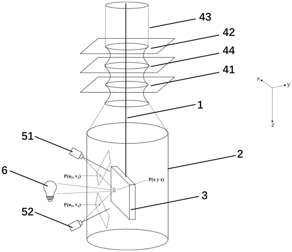
[0023] Such as figure 1 As shown, this embodiment includes a connecting rod 1, a vacuum chamber 2, a sample stage 3. The vacuum cavity 2 has at least ...


PUM


Abstract

The invention provides a sample position holding device for a vacuum cavity, which comprises a vacuum cavity, a connecting rod, a sample table, a displacement table and at least two cameras, wherein the sample table is located at one end of the connecting rod, the other end of the connecting rod is connected with the displacement table through a flange, the vacuum cavity is configured to be at least provided with a partial visible flange window, and the cameras are located outside the vacuum cavity. The camera is configured to photograph a position of the sample table. The binocular vision system is combined with the composite horizontal displacement table, the position of the sample table is corrected in real time, so that the sample is always kept at the rotating center position in the testing process, and the device can be applied to light sources with light spots of different sizes; The high-precision positioning of the sample position in the photoelectron spectroscopy experiment is realized, and the continuous temperature change measurement can be carried out.

Description

Technical field [0001] The present application relates to the field of experimental equipment, and more particularly to a sample position holding device for a vacuum chamber. Background technique [0002] In traditional ultra-high vacuum experimental equipment, such as angular distraction, electronics, etc., the position of the sample to be tested is highly required. However, as the temperature change of the sample table, the sample table in the vacuum chamber will be deformable due to thermal expansion, thereby causing relative movement between the samples on the sample table to the light source. In general, when the temperature changes from 4K (low temperature) to 300K (room temperature), the relative movement of the relative movement occurs in millimeter level, far greater than the light spot and the size of the sample. And this relative displacement causes the sample to deviate from the light source, thereby difficult to perform the relationship characterization of continuous...

Claims


Application Information

Patent Timeline
Patent Type & Authority Applications(China)
IPC IPC(8): G01N23/2204G01N23/2273G01B11/00
CPCG01N23/2204G01N23/2273G01B11/002G01N2223/085G01N2223/309
Inventor 段绍峰杨媛媛黄超之唐天威张文涛
Owner SHANGHAI JIAO TONG UNIV
Why Eureka
Try Eureka