Financial account table and invoice rapid printing device
A printing device and accounting technology, which is applied to printing devices, printing, typewriters, etc., can solve problems such as affecting the printing accounting table and invoice speed, jamming and tearing, and content deviation.
- Summary
- Abstract
- Description
- Claims
- Application Information
AI Technical Summary
Problems solved by technology
Method used
Image
Examples
Embodiment 1
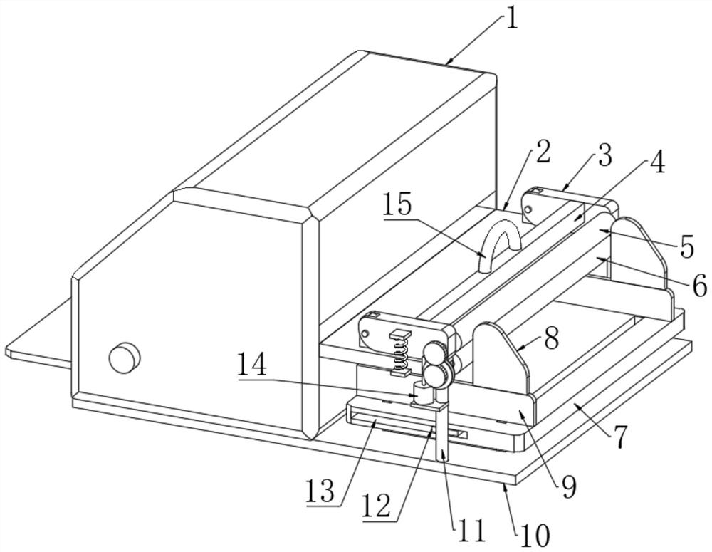
[0028] refer to Figure 1 to Figure 7, a financial account sheet and invoice rapid printing device, comprising a base 10 and a printer body 1 fixed on the upper end of the base 10, the upper end of the base 10 is fixedly connected with two support rods 11, and the upper ends of the two support rods 11 are fixedly connected together There is a horizontal plate 2, one end of the horizontal plate 2 is in contact with the printer body 1, and the other end of the horizontal plate 2 is provided with a gap, and the opposite sides of the gap are connected to the transmission shaft 31 through the first rolling bearing, and the upper end of the horizontal plate 2 passes through The rotating shaft is rotatably connected with two installation rods 3, and the opposite side of the two installation rods 3 is rotatably connected with a support shaft 32 through a second rolling bearing, and the transmission shaft 31 and the shaft wall of the support shaft 32 are all connected with a transmissio...
Embodiment 2
[0030] Embodiment 2: the difference based on Embodiment 1 is;
[0031] refer to Figure 4 to Figure 7 , the transmission mechanism includes a first roller 6 and a second roller 5, the inner wall of the first roller 6 is rotatably connected with the shaft wall of the transmission shaft 31 through two first sealed bearings, and the inner wall of the second roller 5 is connected through two The second sealed bearing is rotatably connected with the shaft wall of the support shaft 32, and the inner walls of the first roller 6 and the second roller 5 are fixedly connected with two annular blocks 30, and the shaft walls of the transmission shaft 31 and the support shaft 32 are all fixed. Two circular rings 36 are connected, and the two circular rings 36 are respectively located between the two annular blocks 30. The inner side of the annular block 30 is fixedly connected with a plurality of evenly distributed clamping blocks 34, and the plurality of clamping blocks 34 together form a...
Embodiment 3
[0033] Embodiment 3: the difference based on embodiment 1 is;
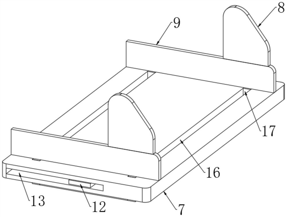
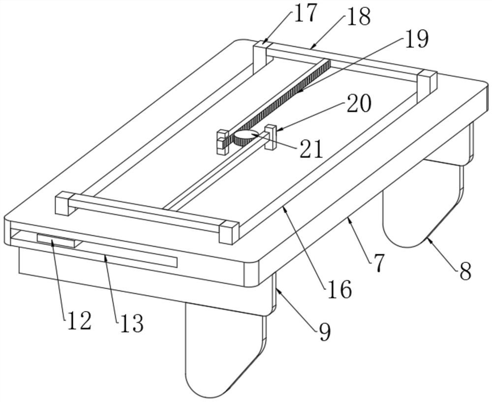
[0034] refer to figure 2 and image 3 , the limiting mechanism includes two transmission rods 18, the two ends of the two transmission rods 18 are fixedly connected with a rectangular rod 17, one end of the rectangular rod 17 passes through the strip-shaped through hole 16 and is fixedly connected with the limiting plate 9, and the placing plate 7 The center of the lower end of the shaft is connected to the rotating shaft through the third rolling bearing, the shaft wall of the rotating shaft is fixedly connected with the ring gear 21, the two sides of the ring gear 21 are meshed with the rack 19, the two racks 19 are parallel to each other, and the rack One end of 19 is fixedly connected with the rod wall of transmission rod 18, and the lower end of placement plate 7 is fixedly connected with two positioning blocks 20, and the opposite side of two positioning blocks 20 is provided with a right-angle gap, and th...
PUM
 Abstract
Description
Claims
Application Information
 - R&D Engineer
- R&D Manager
- IP Professional
- Industry Leading Data Capabilities
- Powerful AI technology
- Patent DNA Extraction
Browse by: Latest US Patents, China's latest patents, Technical Efficacy Thesaurus, Application Domain, Technology Topic, Popular Technical Reports.
© 2024 PatSnap. All rights reserved.Legal|Privacy policy|Modern Slavery Act Transparency Statement|Sitemap|About US| Contact US: help@patsnap.com


