Thin-wall deep-hole cylinder precision forge piece composite forming technology and device
A technology of precision forging and composite forming, applied in forging/pressing/hammer devices, manufacturing tools, swaging presses, etc., which can solve the problems of unfavorable punch later maintenance, inability to install, and idle forging dies.
- Summary
- Abstract
- Description
- Claims
- Application Information
AI Technical Summary
Problems solved by technology
Method used
Image
Examples
Embodiment 1
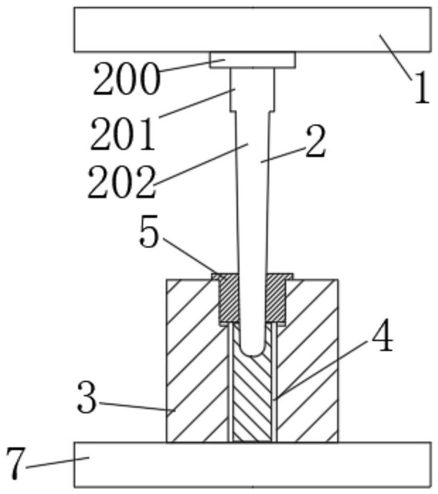
[0065] The embodiment of the present invention provides a thin-walled deep-hole cylinder precision forging compound forming device, such as Figure 1-12 As shown, it includes a moving table 1, a base 7, a drawing punch 2, a drawing die 3 and an upset die 6 matched with the drawing punch 2, and the moving table 1 and the drawing punch Die 2 is detachably connected by connecting device 100, said base 7 is arranged directly below said mobile table 1, said drawing die 3 is fixedly connected on said base 7, and said drawing die 3 is provided with A forging placing groove 4, and a positioning die 5 is set inside the forging placing groove 4;
[0066] The process steps include in turn:
[0067] Step 1: blanking: cut the round steel with the same weight as the finished thin-walled deep-hole cylinder, put it into the forging placement groove 4, and heat the round steel to the temperature required by the process;
[0068] Step 2: Back-extrusion in warm state: put the positioning mold ...
Embodiment 2
[0074] On the basis of the above-mentioned embodiment 1, a driving device is provided on the mobile platform 1, and the driving device is used to drive the position adjustment of the mobile platform 1;
[0075] The drawing punch 2 includes a connecting part 200, a straight part 201 and a working part 202, the two ends of the straight part 201 are respectively fixedly connected to the connecting part 200 and the working part 202, and the connecting part 200 is connected to the working part 202. The mobile station 1 is detachably connected, and the working part 202 is a micro-cone structure;
[0076] The forging placement groove 4 is a stepped deep hole structure, including a mold placement part 400 and a forging placement part 401, the die placement part 400 is located above the forging placement part 401, and has a larger diameter than the forging placement part 401;
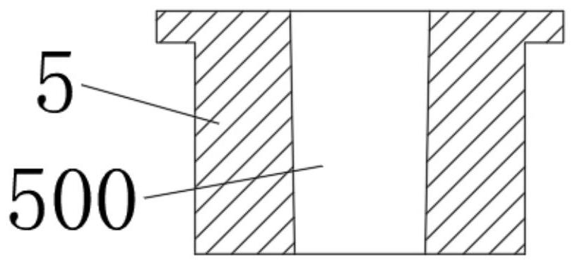
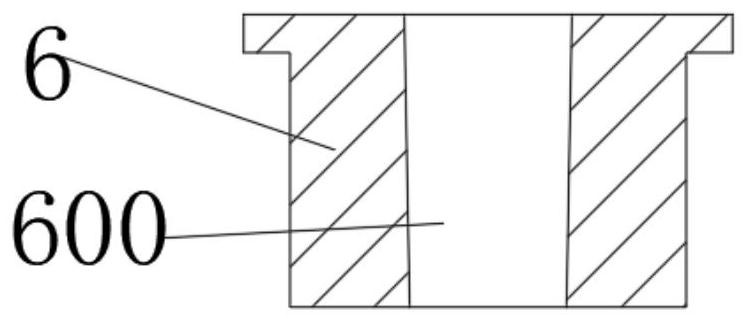
[0077] The upset die 6 and the positioning die 5 are respectively provided with a first through hole 600 and ...
Embodiment 3
[0080] On the basis of Embodiment 1, the mobile platform 1 is provided with a connection hole 101, and the upper end of the drawing punch 2 is provided with two symmetrically arranged engagement grooves 102, and the upper end of the drawing punch 2 is sleeved on the In the connection hole 101, and connected with the mobile station 1 through the connection device 100;
[0081] The connecting hole 101 is provided with a cavity 106 in the circumferential direction, and the connecting device 100 is arranged in the cavity 106. The connecting device 100 includes a snap-fit mechanism, a buffer mechanism and a connecting mechanism arranged symmetrically with respect to the connecting hole 101. device driving mechanism, the connecting device driving mechanism is used to drive the movement of the clamping mechanism and the buffer mechanism, and the clamping mechanism is used to clamp and cooperate with the clamping groove 102 to realize the stretching punch 2 fixed;
[0082] The driv...
PUM
 Abstract
Description
Claims
Application Information
 - R&D
- Intellectual Property
- Life Sciences
- Materials
- Tech Scout
- Unparalleled Data Quality
- Higher Quality Content
- 60% Fewer Hallucinations
Browse by: Latest US Patents, China's latest patents, Technical Efficacy Thesaurus, Application Domain, Technology Topic, Popular Technical Reports.
© 2025 PatSnap. All rights reserved.Legal|Privacy policy|Modern Slavery Act Transparency Statement|Sitemap|About US| Contact US: help@patsnap.com


