
Pipe fitting forming machining method and device for pre-welded bifurcated branch pipes

A bifurcated branch pipe and forming processing technology, which is applied in the direction of feeding device, positioning device, storage device, etc., can solve the problems of poor weld quality and inability to complete welding, optimize the forming process, save the difficulty of welding complex shapes, The effect of reducing complexity

Active Publication Date: 2021-06-25
NANJING UNIV OF AERONAUTICS & ASTRONAUTICS
View PDF6 Cites 3 Cited by
  • Summary
  • Abstract
  • Description
  • Claims
  • Application Information

AI Technical Summary

Problems solved by technology

[0003] The structure of the existing CNC pipe bending machine makes the pipe fittings can only be bent and formed in one time. For the pipe fittings with multiple pre-welded branch pipes, it cannot be formed at one time. It is still necessary to pre-bend each part first, and then manually Connection of branch pipes by welding
If the configuration of the main pipe is too complicated or the branch pipe needs to be welded inside the space configuration, the operation space required for the movement of the welding torch and the transportation of the welding rod will not be satisfied, resulting in poor weld quality or even complete welding.

Method used


Image

  • Pipe fitting forming machining method and device for pre-welded bifurcated branch pipes
  • Pipe fitting forming machining method and device for pre-welded bifurcated branch pipes
  • Pipe fitting forming machining method and device for pre-welded bifurcated branch pipes

Examples


Embodiment Construction

[0038] The present invention will be described in detail below in conjunction with specific embodiments.

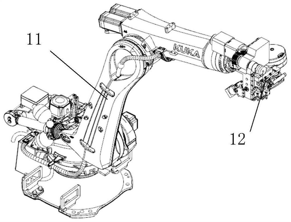
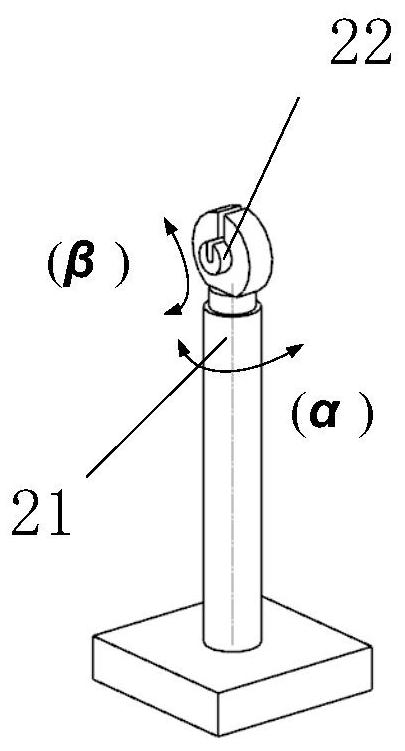
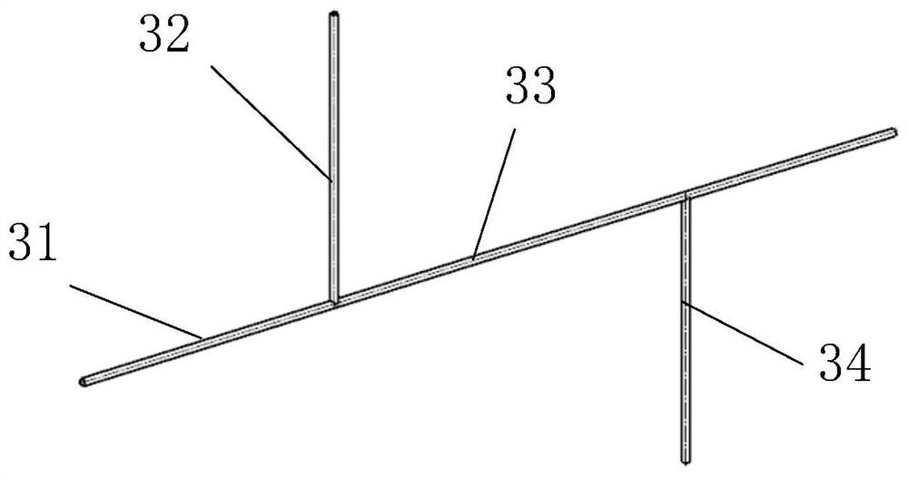
[0039] figure 1 It is a structural schematic diagram of a pipe bending robot in the present invention, figure 2 It is a structural schematic diagram of the clamping and rotating device in the present invention, image 3 It is a structural schematic diagram of the tube blank to be formed in the present invention, Figure 4 It is a schematic diagram of the pipe bending robot clamping the pipe blank in the present invention, Figure 5 It is a schematic diagram of the bending forming of the first part of the main pipe in the present invention, Figure 6 It is a schematic diagram of the position and posture adjustment of the first branch pipe to be bent in the present invention, Figure 7 It is a schematic diagram of the bending and forming of the first branch pipe in the present invention, Figure 8 It is a schematic diagram of the position and attitude adjustment of the ...


PUM


Abstract

The invention discloses a pipe fitting forming machining method and device for pre-welded bifurcated branch pipes. The pipe fitting forming machining device comprises a pipe bending robot and a clamping rotating device. A tail end bending forming device is used for conducting bending forming on pipe blanks according to a system instruction, the clamping rotating device comprises a clamping device, a first rotating shaft and a second rotating shaft, the clamping device is installed on the second rotating shaft, and the second rotating shaft can drive the clamping device to rotate around the horizontal axis; and the first rotating shaft can drive the second rotating shaft and the clamping device to rotate around the vertical axis together, the clamping device is used for clamping a main pipe of the pipe blanks, and the first rotating shaft and the second rotating shaft are matched with the pipe bending robot to adjust the positions and postures of the pipe blanks and rotate in a linkage mode. The problem of integral bending forming of a component with a plurality of forked branch pipes is solved; and economical benefits are obvious, efficiency is high, and intelligent bending forming is achieved.

Description

technical field [0001] The present invention relates to the technical field of pipe bending processing, in particular to a pipe fitting processing method and forming device based on a digital intelligent robot for pre-welding bifurcated branch pipes. Background technique [0002] At present, the automatic forming equipment for pipe bending processing is usually a CNC pipe bending machine, and the pipe forming process is often the bending of a single pipe, which needs to be connected manually by joints or welding. [0003] The structure of the existing CNC pipe bending machine makes the pipe fittings can only be bent and formed in one time. For the pipe fittings with multiple pre-welded branch pipes, it cannot be formed at one time. It is still necessary to pre-bend each part first, and then manually Connect the branch pipes by welding. If the configuration of the main pipe is too complicated or the branch pipe needs to be welded inside the space configuration, the operation...

Claims


Application Information

Patent Timeline
Patent Type & Authority Applications(China)
IPC IPC(8): B21D7/16B21D7/12B21D43/00
CPCB21D7/16B21D7/12B21D43/003
Inventor 刘春梅郭训忠黄祖树郑硕程诚
Owner NANJING UNIV OF AERONAUTICS & ASTRONAUTICS
Learn More