
Two-component servo metering cylinder

A metering cylinder and two-component technology, which is applied in coatings and devices for coating liquid on the surface, etc., can solve the problem that the viscosity of glue is very sensitive to changes in temperature, cannot adapt to the requirements of the process flow, and the two-group glue applicator cannot guarantee the dispensing Issues such as specific accuracy and repeatability

Active Publication Date: 2021-06-25
上海大项科技有限公司
View PDF9 Cites 1 Cited by
  • Summary
  • Abstract
  • Description
  • Claims
  • Application Information

AI Technical Summary

Problems solved by technology

[0004] 1. Since the viscosity of the glue is very sensitive to changes in temperature and has a large deviation, the so-called simultaneous release of glue by traditional equipment is actually due to changes in viscosity (including changes in the glue itself of components A and B and changes in viscosity between A and B glues) Poor), the actual amount of glue released is different at different temperatures;
[0005] 2. When a power source pushes the two-component proportional cylinder to output glue, due to the difference in viscosity, the low-viscosity glue will enter the mixing pipe before the high-viscosity glue when the glue mixing valve is opened, and vice versa when the glue mixing valve is closed. Synchronously output and close glue;
[0006] 3. The proportional cylinder and the rubber mixing valve are connected by a hose, the hose part will be longer, and the error caused by the deformation of each hose itself will increase;
[0007] Since the existing two-group gluing machine cannot guarantee the accuracy of the ratio and the reliability of the repetition, it is completely unable to meet the requirements of the modern process. Therefore, a two-component servo metering cylinder is proposed.

Method used


Image

  • Two-component servo metering cylinder
  • Two-component servo metering cylinder
  • Two-component servo metering cylinder

Examples


Embodiment Construction

[0024] In order to make the purpose, technical solutions and advantages of the embodiments of the present invention more clear, the technical solutions in the embodiments of the present invention will be clearly and completely described below in conjunction with the drawings in the embodiments of the present invention. Accordingly, the following detailed description of the embodiments of the invention provided in the accompanying drawings is not intended to limit the scope of the claimed invention, but merely represents selected embodiments of the invention. Based on the embodiments of the present invention, all other embodiments obtained by persons of ordinary skill in the art without creative efforts fall within the protection scope of the present invention.

[0025] In the description of the present invention, it should be noted that the orientation or positional relationship indicated by the terms "center", "upper", "lower", "vertical", "horizontal", "inner" and "outer" are...


PUM


Abstract

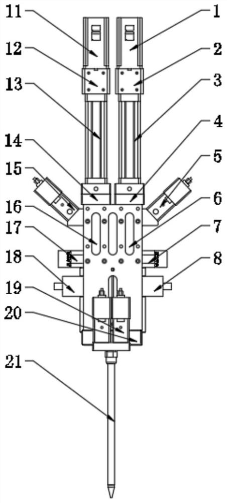
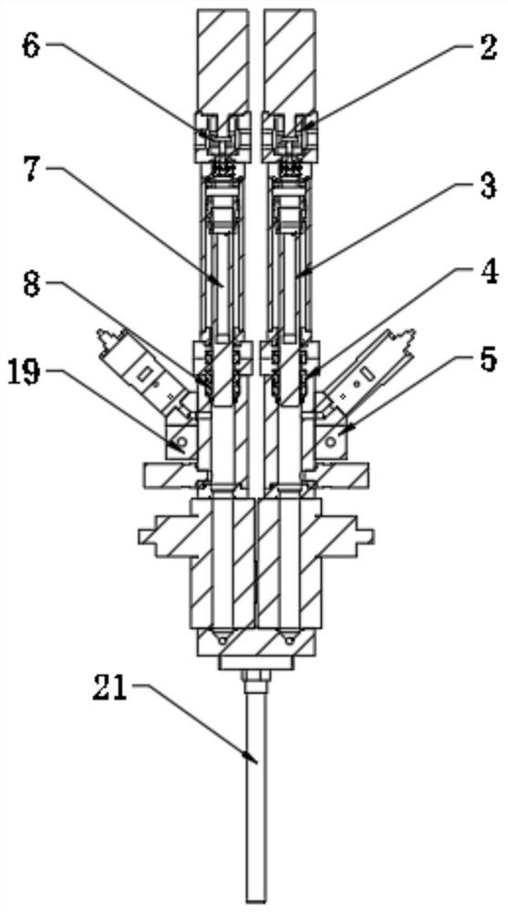
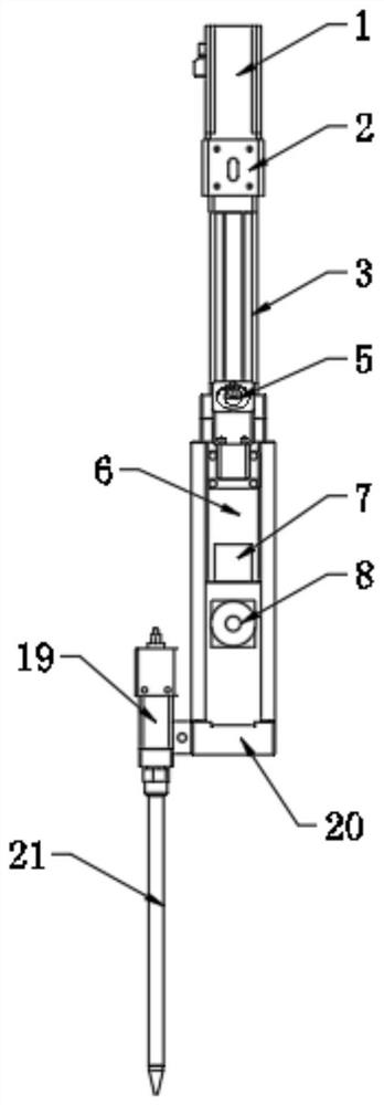
The invention belongs to the technical field of gluing equipment, and particularly relates to a two-component servo metering cylinder which comprises a glue supply mechanism A and a glue supply mechanism B. The glue supply mechanism A comprises a first servo motor, and a first electric cylinder body is fixedly installed at the bottom of the first servo motor. An output shaft of the first servo motor is fixedly connected with an input shaft of the first electric cylinder body, a first main cylinder body is fixedly installed at the bottom of the first electric cylinder body, and a first glue inlet valve is fixedly installed at one side of the first main cylinder body. According to the two-component servo metering cylinder, a sewing device is directly installed at the tail end of the equipment and directly connected with a glue mixing pipe, no hose transition exists in the middle, the influence of a pipeline system on double-component matching metering is thoroughly eliminated, the influences of viscosity, temperature, the mixing ratio and gun stopping interval time are avoided, the matching is accurate, the proportion is adjustable, and proportioning errors caused by factors such as temperature / pipeline / pressure changes in the double-component glue automatic gluing process are thoroughly solved.

Description

technical field [0001] The invention relates to the technical field of gluing equipment, in particular to a two-component servo metering cylinder. Background technique [0002] In the existing two-component glue applicator system, most of the glue mixing equipment of traditional manufacturers adopts a fixed ratio metering cylinder, and uses the same power source (pneumatic or electric) to push out A / B at the same time. Two-component glue, then the glue passes through a certain length of hose through the glue valve, into the glue pipe, and finally applied to the workpiece. [0003] But, existing two-group gluing machine also has following shortcoming: [0004] 1. Since the viscosity of the glue is very sensitive to changes in temperature and has a large deviation, the so-called simultaneous release of glue by traditional equipment is actually due to changes in viscosity (including changes in the glue itself of components A and B and changes in viscosity between A and B glues...

Claims


Application Information

Patent Timeline
IPC IPC(8): B05C11/10
CPCB05C11/1036B05C11/1002
Inventor 李成文刘俊
Owner 上海大项科技有限公司
Learn More