
High-flux material synthesis equipment and method based on micro-fluidic chip

A technology of microfluidic chips and synthesis equipment, which is applied in chemical instruments and methods, feeding devices, control/regulation processes, etc., can solve the problems of poor material repeatability, low accuracy and controllability of reaction parameters, and low research efficiency, etc. Achieve the effect of improving the preparation accuracy, reliable microfluidic high-throughput synthesis and detection process, and shortening the preparation cycle

Inactive Publication Date: 2021-06-25
SHANGHAI INST OF CERAMIC CHEM & TECH CHINESE ACAD OF SCI
View PDF5 Cites 2 Cited by
  • Summary
  • Abstract
  • Description
  • Claims
  • Application Information

AI Technical Summary

Problems solved by technology

[0006] Aiming at the problems that existing material preparation and synthesis research requires manual operation, low precision and controllability of reaction parameters, low research efficiency and poor material repeatability, the purpose of the present invention is to provide a rapid, fully automatic and continuous production of materials. Fluidic high-throughput material synthesis equipment and method

Method used


Image

  • High-flux material synthesis equipment and method based on micro-fluidic chip
  • High-flux material synthesis equipment and method based on micro-fluidic chip
  • High-flux material synthesis equipment and method based on micro-fluidic chip

Examples


Embodiment Construction

[0051] The present invention will be further described below in conjunction with the drawings and the following embodiments. It should be understood that the drawings and the following embodiments are only used to illustrate the present invention rather than limit the present invention.

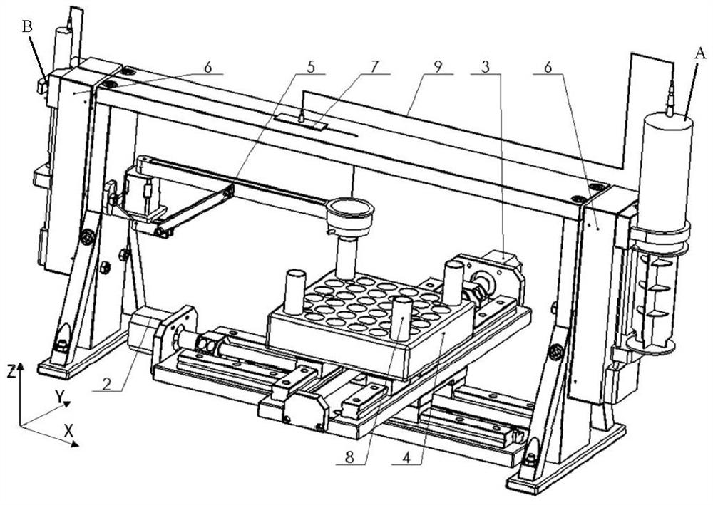
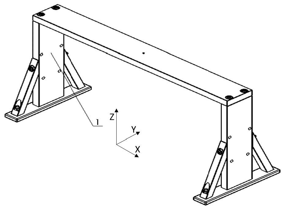
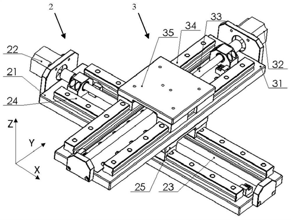
[0052] A high-throughput material synthesis device based on a microfluidic chip is provided here. figure 1 It is a schematic diagram of the overall structure of a high-throughput material synthesis device according to an embodiment of the present invention. The following will figure 1 The left-right direction when the middle face is viewed towards the gantry support 1 is defined as the first axis direction, that is, the X-axis direction, and the front-rear direction that is orthogonal to the X-axis direction in the horizontal plane is defined as the second axis direction, that is, the Y-axis direction, and the orthogonal The up and down vertical extension direction of the horizontal plane fo...


PUM


Abstract

The invention provides high-flux material synthesis equipment and method based on a micro-fluidic chip. The equipment comprises a bracket with a suspended part, at least two injection pump mechanisms arranged on the bracket and filled with original samples, a micro-fluidic chip arranged at the suspended part of the bracket, a pipeline connected with the micro-fluidic chip and the injection pump mechanism, an objective table, a moving device and a control device; at least two original sample injection ports of the micro-fluidic chip are correspondingly connected with the injection pump mechanism; the objective table is arranged below the micro-fluidic chip and carries array test tubes; the moving device is used for moving the objective table on a horizontal plane; and the control device can enable the moving device to drive the objective table to move until one test tube is positioned right below a sample outflow port, and can enable the specified injection pump mechanism to be synchronously started, so that original samples separately enter a pipeline assembly and react to obtain a group of reaction samples, and the group of reaction samples flow into one corresponding test tube. Therefore, various materials can be prepared and collected into each test tube at one time.

Description

technical field [0001] The invention relates to the field of material preparation, and specifically designs a high-throughput material synthesis device and method based on a microfluidic chip. Background technique [0002] At present, my country has achieved fruitful results in nano-drug carriers and related biomaterials in recent years, but it is still difficult to promote industrialization research. The main reason is that the synthesis methods based on small containers such as hydrothermal and stirring in the laboratory are difficult to scale up production in batches. At the same time, the trial-and-error method of multiple sequential iterations in the development of materials in the traditional laboratory also seriously hinders nanotechnology. The process and speed of drug carrier research and development, so it is urgent to introduce new models to speed up the process of material research and development from basic to application. [0003] Microfluidic synthesis techno...

Claims


Application Information

Patent Timeline
Patent Type & Authority Applications(China)
IPC IPC(8): B01J4/00B01J4/02B01J19/00
CPCB01J4/001B01J4/008B01J4/02B01J19/0006B01J19/0093B01J2204/002B01J2219/00894B01J2204/005
Inventor 马明兰正义陈航榕
Owner SHANGHAI INST OF CERAMIC CHEM & TECH CHINESE ACAD OF SCI
Learn More