
Floor slab, bidirectional stiffening rigid part and flange plate overhanging web shear type replaceable energy-consuming beam section laminated connection combined joint

A technology of combining joints and flange plates, which is applied to building components, building types, earthquake resistance, etc., can solve problems such as increased cost of structure demolition and repair, concrete shedding, overall collapse, etc., and achieves convenient design, weak shear stiffness, and lightening damage effect

Active Publication Date: 2021-06-22
BEIJING UNIV OF TECH
View PDF7 Cites 1 Cited by
  • Summary
  • Abstract
  • Description
  • Claims
  • Application Information

AI Technical Summary

Problems solved by technology

However, under the action of earthquakes, the structure often forms a system due to plastic hinges generated at the column ends, and then the overall instability or overall collapse occurs. Through reasonable structural design and construction measures, the plastic hinges can be transferred from the column ends to the beam ends. The increased deformation of the beam end will cause a large number of crack damage to the concrete floor, and in severe cases, it will cause a large area of ​​concrete to fall off, resulting in a significant increase in the cost of demolition and repair of the structure after the earthquake

Method used


Image

  • Floor slab, bidirectional stiffening rigid part and flange plate overhanging web shear type replaceable energy-consuming beam section laminated connection combined joint
  • Floor slab, bidirectional stiffening rigid part and flange plate overhanging web shear type replaceable energy-consuming beam section laminated connection combined joint
  • Floor slab, bidirectional stiffening rigid part and flange plate overhanging web shear type replaceable energy-consuming beam section laminated connection combined joint

Examples


Embodiment Construction

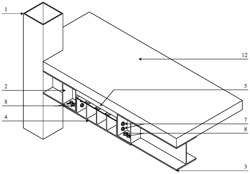
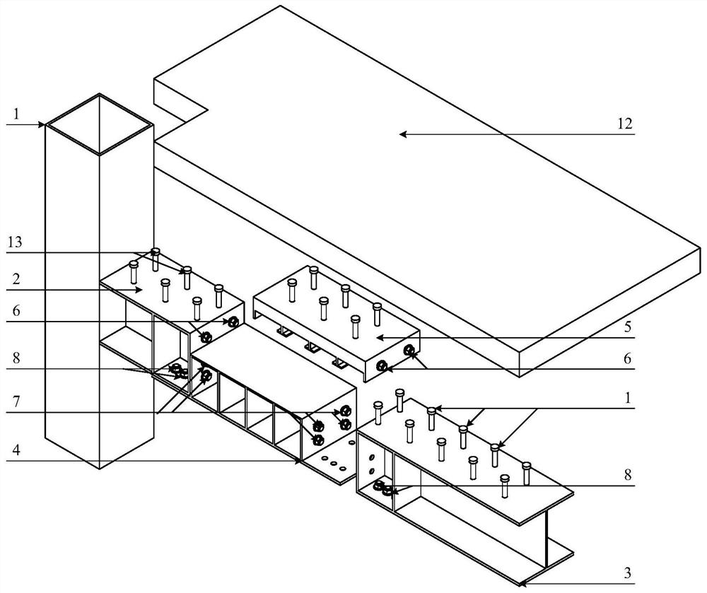
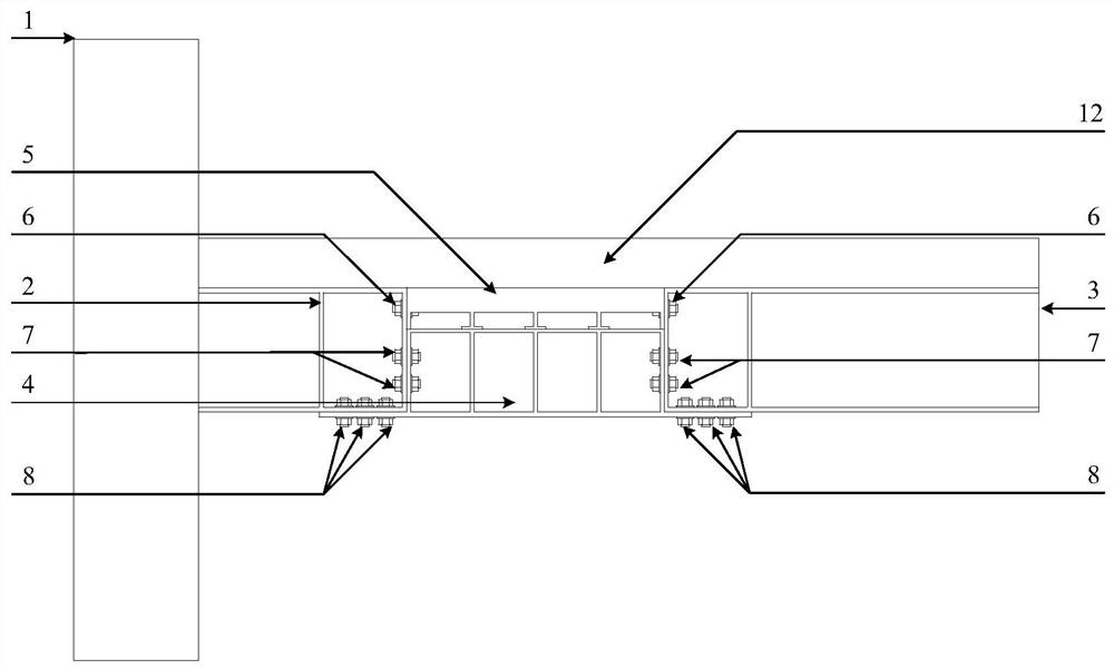
[0018] Attached below Figure 1~5 , detailing the implementation of this patent.

[0019] Such as Figure 1~5 As shown, a composite joint of floor slab, two-way stiffening rigid member and flange plate with extended web shear type replaceable energy-dissipating beam segment laminated connection includes the following components:

[0020] 1——square steel column

[0021] 2 - cantilever beam section

[0022] 3——Middle beam section

[0023] 4——External web shearing type replaceable energy-dissipating beam section of flange plate

[0024] 5——Two-way stiffening rigid parts

[0025] 6——The first high-strength bolt group

[0026] 7——The second high-strength bolt group

[0027] 8——The third high-strength bolt group

[0028] 9——transverse stiffener

[0029] 10——Longitudinal stiffener

[0030] 11——Pallet

[0031] 12 - concrete floor

[0032] 13 - pegs

[0033] 14——The lower flange plate of energy-dissipating beam section can be replaced

[0034] 15——The upper flange plate of ...


PUM


Abstract

The invention discloses a floor slab, bidirectional stiffening rigid part and flange plate overhanging web shear type replaceable energy-consuming beam section laminated connection combined joint, and belongs to the technical field of structural engineering. The beam column joint comprises a cantilever beam section, a middle beam section, a bidirectional stiffening rigid part, a flange plate overhanging web shear type replaceable energy-consuming beam section, a concrete floor slab and a high-strength bolt. The welding part of the beam column joint is completed in a factory, and the welding quality is easy to control. In the aspect of mechanical properties, the arrangement of the bidirectional stiffening rigid part and the flange plate overhanging web shear type replaceable energy-consuming beam section can change the rigidity distribution of the joint, so that the height of a neutral axis at the joint is increased, and the damage to the concrete floor slab is reduced; and meanwhile, the plastic damage of the joint is mainly concentrated on a web of the flange plate overhanging web shear type replaceable energy-consuming beam section, and the post-earthquake function recovery of the structure can be realized only by disassembling the high-strength bolt and replacing the flange plate overhanging web shear type replaceable energy-consuming beam section after an earthquake.

Description

technical field [0001] The patent relates to a combined node of a floor slab, a two-way stiffening rigid member and a flange plate with a shear-type replaceable energy-dissipating beam section laminated connection, which belongs to the technical field of structural engineering. Background technique [0002] Steel structure buildings have become one of the key promotion projects in my country's residential industrialization projects due to their light weight, good seismic performance, industrial production, and prefabricated installation. However, under the action of earthquakes, the structure often forms a system due to plastic hinges generated at the column ends, and then the overall instability or overall collapse occurs. Through reasonable structural design and construction measures, the plastic hinges can be transferred from the column ends to the beam ends. As the deformation of the beam ends increases, a large number of cracks will be damaged in the concrete floor slab...

Claims


Application Information

Patent Timeline
Patent Type & Authority Applications(China)
IPC IPC(8): E04H9/02E04B1/98
CPCE04H9/021E04H9/024E04B1/98
Inventor 姜子钦李祥源阎田周宝儒王汉文
Owner BEIJING UNIV OF TECH
Learn More