A prefabricated lightweight partition wall slat connection device using double dovetail connection
A technology of light-weight partition wall slats and connecting devices, which is applied in walls, passive houses, buildings, etc., can solve the problems of troublesome use, light and weak connection of connecting structures, and difficult secondary disassembly, etc., so as to reduce the difficulty of operation, Reduce construction time and facilitate dismantling
- Summary
- Abstract
- Description
- Claims
- Application Information
AI Technical Summary
Problems solved by technology
Method used
Image
Examples
Embodiment 1
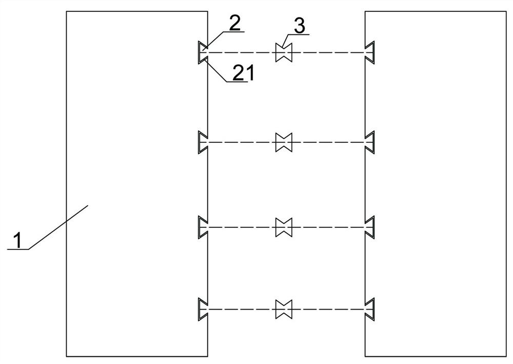
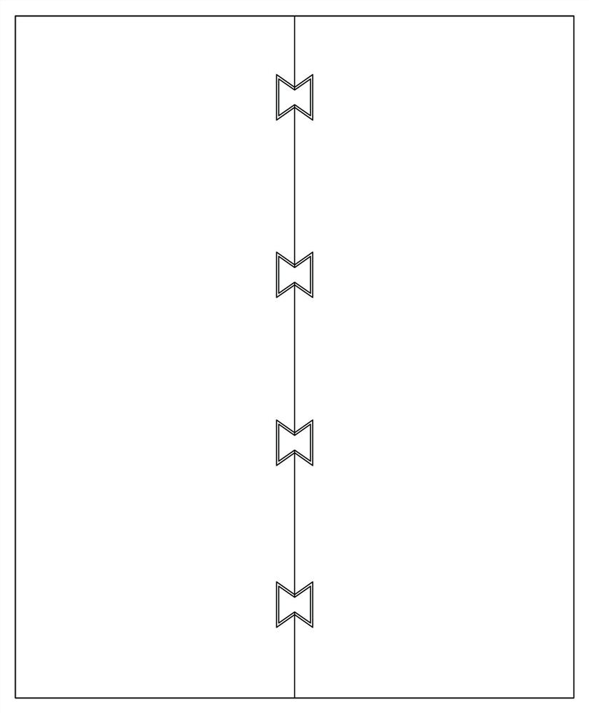
[0029] Embodiment 1: This embodiment aims to provide a prefabricated lightweight partition wall strip connection device using double dovetail connections, which is mainly used for the combined assembly and installation of lightweight partitions. In view of the defects existing in the existing structure, As a result, after the installation of the lightweight partition is completed, it is easy to generate a gap between the two panels, which is troublesome to use and cannot be replaced twice. Based on this, this embodiment connects two or more sets of lightweight partitions through double dovetail connectors. The effective and reliable connection of the wall battens increases the necessary constraints to form an integral wall. Because the relative deformation between the two lightweight partition wall slabs is limited, it can effectively avoid the decrease of connection durability and overall stability caused by mortar cracking, and the construction of the connection is simple, av...
Embodiment 2
[0034]Embodiment 2: This embodiment is basically the same as Embodiment 1, and the difference is that this embodiment further limits the structure of the connector.
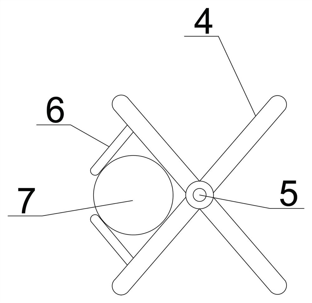
[0035] This example Figure 3-4 As shown in , wherein the connector 2 includes a driving arm 4 and a driving structure, the middle parts of the two driving arms 4 are hinged together through the main hinge shaft 5, and a driving structure that forces them to expand is arranged between the two driving arms 4; specifically for the above purpose , the moving structure includes a baffle and an air bag; the baffle is correspondingly arranged inside the driving arm, and an air bag cavity is formed between the driving arm, and the air bag is arranged in the air bag cavity, and when the air bag is filled with gas, it can expand to drive the arms spread out.
[0036] Specifically, the inner side of the baffle is set as an inclined plane. In order to further improve the driving effect of the airbag, the airbag has a figur...
Embodiment 3
[0038] Embodiment 3: This embodiment is basically the same as Embodiment 2, the difference is that this embodiment provides a second implementation of the driving structure.
[0039] Such as Figure 5-6 As shown, the second embodiment is: the drive structure includes a power arm 8 and a drive rod; the outer ends of the two power arms 8 are hinged at the outer ends of the drive arm 4, and the inner ends of the two power arms 8 are hinged together through the auxiliary hinge shaft 9 , the driving rod comprises a driving sleeve 10, a left connecting rod 13 and a right connecting rod 12, the two ends of the driving sleeve 10 are threadedly connected to the inner ends of the left connecting rod 13 and the right connecting rod 12, and the left connecting rod 13 and the Right connecting rod 12 threads are arranged in the opposite direction; the outer ends of left connecting rod 13 and right connecting rod 12 are respectively fixed on the main hinge shaft 5 and the auxiliary hinge sha...
PUM
 Abstract
Description
Claims
Application Information
 - R&D
- Intellectual Property
- Life Sciences
- Materials
- Tech Scout
- Unparalleled Data Quality
- Higher Quality Content
- 60% Fewer Hallucinations
Browse by: Latest US Patents, China's latest patents, Technical Efficacy Thesaurus, Application Domain, Technology Topic, Popular Technical Reports.
© 2025 PatSnap. All rights reserved.Legal|Privacy policy|Modern Slavery Act Transparency Statement|Sitemap|About US| Contact US: help@patsnap.com


