Mold for injection molding of plastic water cup

A water cup and mold technology, applied in the field of production and manufacturing, can solve problems affecting product quality, large floor space, surface scratches, etc., and achieve the effect of prolonging the injection molding time, ensuring the effect, and avoiding the incomplete cup

Active Publication Date: 2021-06-22
佛山市鑫斐翔精密模具有限公司
View PDF6 Cites 0 Cited by
  • Summary
  • Abstract
  • Description
  • Claims
  • Application Information

AI Technical Summary

Problems solved by technology

[0002] In the production process of the water cup, since the mold usually adopts the form of lying on its side, which occupies a large area, it is very unfriendly to places with large space restrictions. At the same time, the usual mold only uses ejector pins when removing the film. It is often difficult to remove the film, and it is easy to scratch the surface, which affects the product quality. After the film is removed, it is collected in the form of free fall, which is easy to cause losses

Method used


Image

  • Mold for injection molding of plastic water cup
  • Mold for injection molding of plastic water cup
  • Mold for injection molding of plastic water cup

Examples


Embodiment Construction

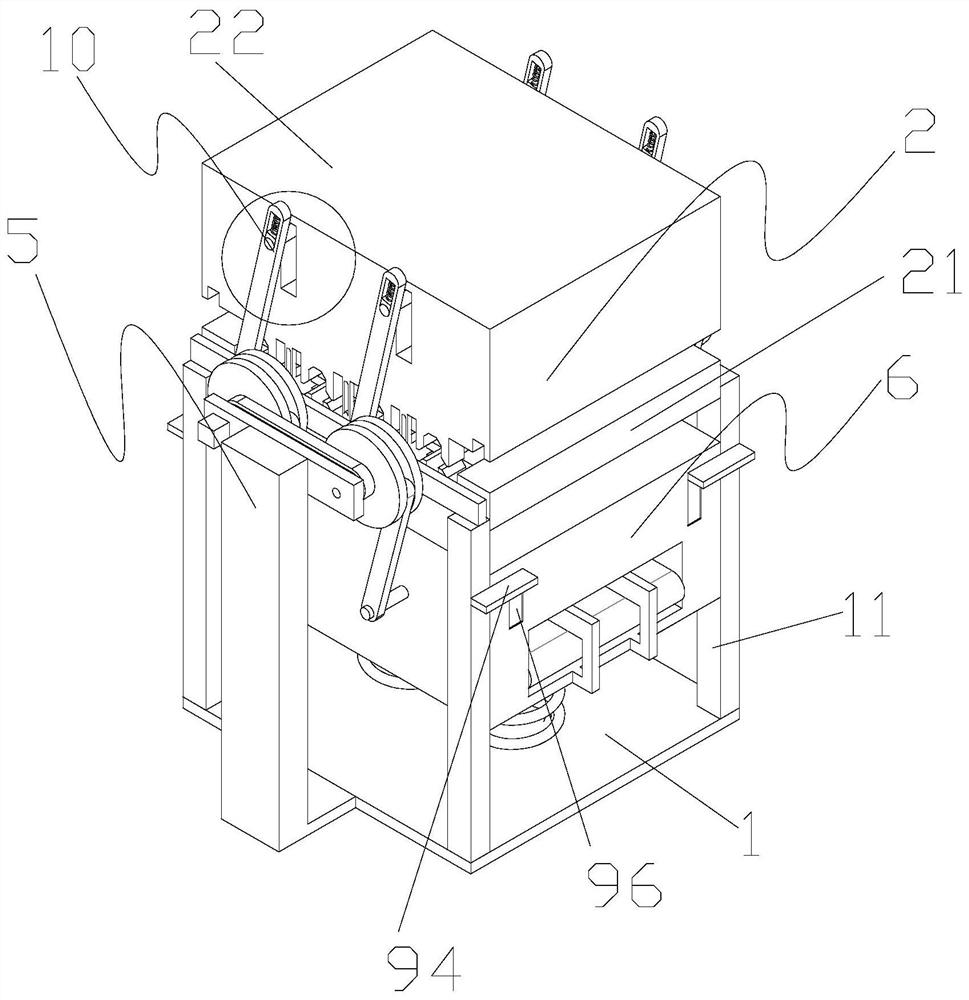
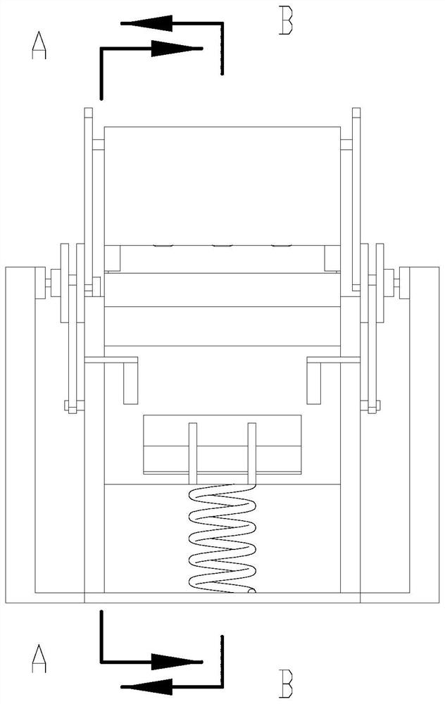
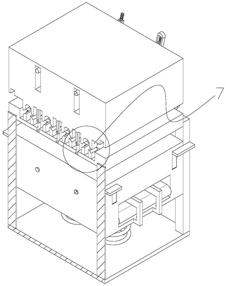
[0029] Such as Figure 1-15 As shown, a plastic water cup injection molding mold includes a base plate 1, a column 11, and a water cup injection device 2; the column 11 is erected on the base plate 1, and the water cup injection device 2 is located on the column 11; Module 21, upper module 22, cylinder 23, limit block 24, limit groove 25, split cavity 3, injection molding core 4, transmission structure 5, material receiving structure 6; the lower module 21 is fixedly connected to the column 11, The upper module 22 is arranged above the lower template, and a plurality of cylinders 23 are arranged on both sides of the lower module 21. The limiting block 24 is arranged below the upper module 22, and the limiting groove 25 is opened in the limiting block. 24, the split-type cavity 3 is set on the lower module 21, the injection molding core 4 is set on the upper module 22, the transmission structure 5 is used to drive the upper module 22 to move up and down, and the material receiv...


PUM


Abstract

The invention discloses a mold for injection molding of a plastic water cup. The mold comprises a bottom plate, a stand column vertically arranged on the bottom plate and a water cup injection molding device arranged on the stand column; the water cup injection molding device comprises a lower die block fixedly connected to the stand column, an upper die block arranged above the lower die block, a plurality of cylinders arranged on the two sides of the lower die block, limiting blocks arranged below the upper die block, limiting grooves formed in the limiting blocks, a split type cavity formed in the lower die block, an injection molding core arranged on the upper die block, a transmission structure used for driving the upper module to move up and down and a material receiving structure arranged below the lower module and has a cooling function; the limiting grooves sleeve the cylinders in a one-to-one correspondence manner; the moving directions of the upper die block and the material receiving structure are opposite; through the arrangement of the material receiving structure, the produced plastic water cup is effectively received; the situation that the water cup flies out of the mold to cause material damage is avoided; and meanwhile, through the arrangement of the split type cavity, the demolding efficiency is improved.

Description

technical field [0001] The invention belongs to the technical field of production and manufacturing, and in particular relates to a mold for plastic water cup injection molding. Background technique [0002] In the production process of the water cup, since the mold usually adopts the form of lying on its side, which occupies a large area, it is very unfriendly to places with large space restrictions. At the same time, the usual mold only uses ejector pins when removing the film. It is often difficult to remove the film, and it is easy to scratch the surface, which affects the product quality. After the film is removed, it is collected in the form of free fall, which is easy to cause losses. Contents of the invention [0003] In order to overcome the deficiencies in the prior art, the present invention provides a mold for plastic water cup injection molding. [0004] In order to achieve the above object, the present invention adopts the following technical solutions: a mo...

Claims


Application Information

Patent Timeline
Patent Type & Authority Applications(China)
IPC IPC(8): B29C45/17B29C45/26B29C45/40
CPCB29C45/1769B29C45/26B29C45/40B29L2031/7132
Inventor 范佳康
Owner 佛山市鑫斐翔精密模具有限公司
Why Eureka
Try Eureka