Cutting device

A technology of cutting device and cutting table, which is applied in the field of cutting, can solve the problems of poor material position accuracy, sorting of difficult-to-cut pieces, poor quality stability of cut pieces, etc., and achieve the effect of improving production efficiency and stable quality

Pending Publication Date: 2021-06-22
SINOMECH CORP
View PDF0 Cites 1 Cited by
  • Summary
  • Abstract
  • Description
  • Claims
  • Application Information

AI Technical Summary

Problems solved by technology

After cutting, it is difficult to sort the cut pieces because the material and the cut pieces are on the same platform
In the prior art, vacuum adsorption is used to suck out the cut sheet, but this method will destroy the traction tension of the material, resulting in poor position accuracy of the material in the next cutting, and poor quality stability of the cut sheet, which cannot Meet the production needs of enterprises

Method used


Image

  • Cutting device
  • Cutting device
  • Cutting device

Examples


Embodiment Construction

[0020] The specific implementation manners of the present invention will be further described in detail below in conjunction with the accompanying drawings and embodiments. The following examples are used to illustrate the present invention, but are not intended to limit the scope of the present invention.

[0021] In the description of the present invention, it should be noted that the terms "center", "longitudinal", "transverse", "upper", "lower", "front", "rear", "left", "right", " The orientations or positional relationships indicated by "vertical", "horizontal", "top", "bottom", "inner", "outer", etc. are based on the orientation or positional relationships shown in the drawings, and are only for the convenience of describing the present invention and simplifying Describes, but does not indicate or imply that the device or element referred to must have a specific orientation, be constructed in a specific orientation, and operate in a specific orientation, and therefore sh...


PUM


Abstract

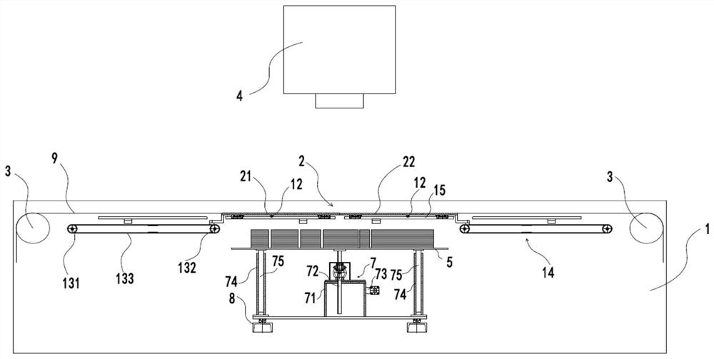
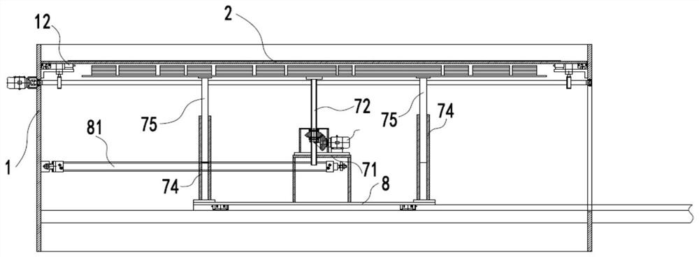
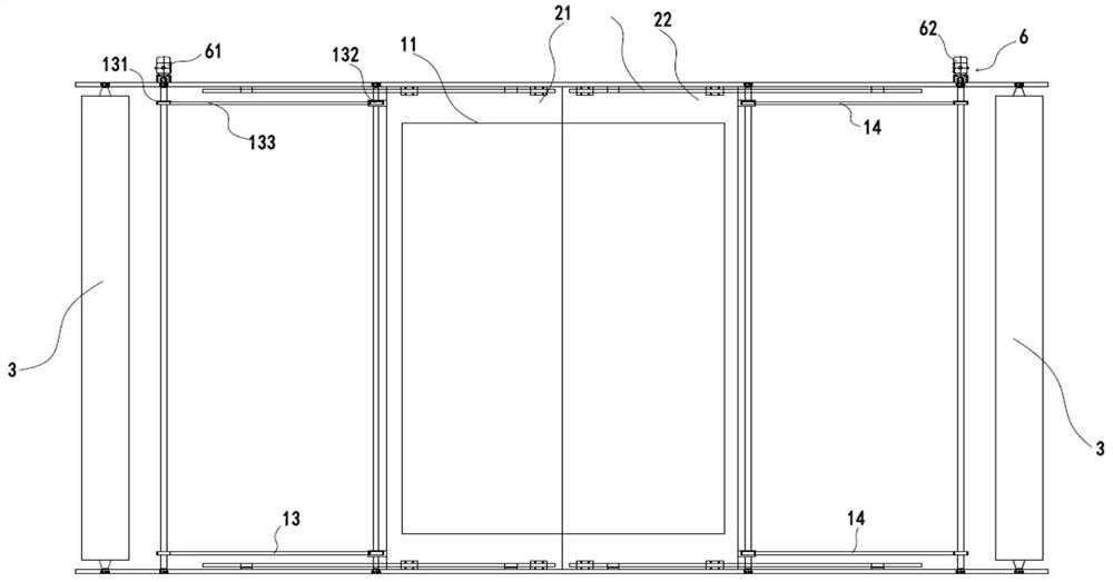
The invention relates to the technical field of cutting, and discloses a cutting device which comprises a machine frame, a cutting table, a traction roller, a laser, a stacking table and a first driving mechanism. The cutting table is arranged on the machine frame and can be located on a cutting position; the traction roller is arranged on the machine frame and guides materials to pass through the cutting position, and the cutting table supports the materials; when the materials are located at the cutting position, the laser cuts the materials; the stacking table is arranged below the cutting position; and the first driving mechanism drives the cutting table, so that the cutting table can leave and return to the cutting position. According to the embodiment of the cutting device, cut sheet materials can be can sorted out without damaging traction tension of subsequent materials, so that the influence on the position precision of the subsequent materials is avoided, the stable quality of the cut sheet materials is ensured, and the production efficiency is improved.

Description

technical field [0001] The invention relates to the technical field of cutting, in particular to a cutting device. Background technique [0002] When cutting flexible coils or continuous materials with laser, because the material is relatively soft, it needs to be cut under a small tension. Usually, the flexible roll is placed on a cutting table, and the cutting table supports the material to ensure that the material is flat during cutting. No wrinkling, no stretch deformation. After cutting, since the material and the cut pieces are all on the same platform, it is difficult to sort the cut pieces out. In the prior art, vacuum adsorption is used to suck out the cut sheet, but this method will destroy the traction tension of the material, resulting in poor position accuracy of the material in the next cutting, and poor quality stability of the cut sheet, which cannot Meet the production needs of enterprises. Contents of the invention [0003] The purpose of the present i...

Claims


Application Information

Patent Timeline
Patent Type & Authority Applications(China)
IPC IPC(8): B26F3/16B26D7/20B26D7/32
CPCB26D7/20B26D7/32B26F3/16
Inventor 白广志任继平
Owner SINOMECH CORP
Why Eureka
Try Eureka