Table Saw Fence With Adjustment Mechanism

A fence and angle adjustment technology, used in manufacturing tools, sawing machines, sawing components, etc., can solve the problem of difficulty in adjusting the position of the fence, and achieve the effect of straight cutting and reproducible cutting

Pending Publication Date: 2021-06-22
ROBERT BOSCH GMBH
View PDF0 Cites 0 Cited by
  • Summary
  • Abstract
  • Description
  • Claims
  • Application Information

AI Technical Summary

Problems solved by technology

However, it can be difficult to adjust the position of the fence so that the leading surface of the fence has parallelism with respect to the blade

Method used


Image

  • Table Saw Fence With Adjustment Mechanism
  • Table Saw Fence With Adjustment Mechanism
  • Table Saw Fence With Adjustment Mechanism

Examples


Embodiment Construction

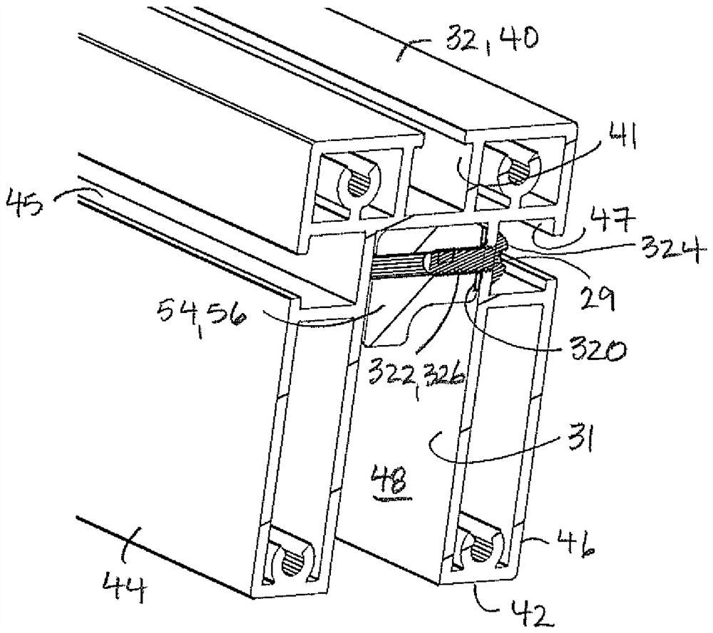
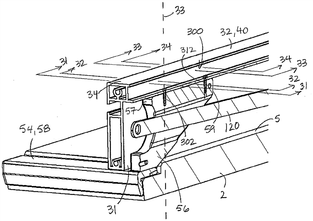
[0061] refer to Figure 1 to Figure 7 , the saw device 1 comprises a table top 2 and a fence assembly 30 supported on the saw device 1 such that the fence 32 overlies the table top 2 and extends parallel to the cutting blade 8 of the saw device 1 . The saw device 1 illustrated in the figures is, for example, a table saw, although in other embodiments the saw device 1 may be configured as another type of cutting tool, wherein the fence assembly is used to place the workpiece (not shown) relative to the blade 8. shown) positioned on the surface. The saw table top 2 is part of a saw table or cabinet structure (not shown) and defines a flat work surface 5 for supporting a workpiece. The table top 2 includes an opening 6 . A blade 8 of the saw device 1 , eg a circular saw blade, protrudes through the opening 6 and an insert 9 is disposed in the opening 6 between the blade and the working surface 5 . A motor (not shown) is housed inside the cabinet of the saw device 1 and is conf...


PUM


Abstract

A table saw fence with an adjustment mechanism is provided. A fence assembly configured to guide a workpiece with respect to a blade of a saw device includes a fence that is supported by rails for sliding movement relative to a work surface. Opposed ends of the fence are supported on the rails via rail engagement members. The fence assembly includes a fence angle adjustment mechanism associated with a housing of one of the rail engagement members. The fence angle adjustment mechanism includes biasing elements working in conjunction with an adjustment screw to adjust the position of the fence with respect to parallelism to the blade.

Description

Background technique [0001] Table saws of various designs include a frame and an upwardly facing work surface having an opening through which the blade extends. Table saws may include a movable fence supported on one or more rails disposed on opposite sides of the work surface. The fence provides a guide surface against which the material to be cut is positioned. The fence may be positioned relative to the work surface by sliding the fence along the track to a desired spacing from the blade and using a locking mechanism to secure the fence in the desired position. During a cutting operation, the material rests on the work surface while sliding along the fence as it is cut by the saw blade. When the fence's leading surface is arranged perpendicular to the work surface and aligned parallel to the blade, the fence enables a table saw to provide accurate, straight and reproducible cuts. However, it can be difficult to adjust the position of the fence such that the leading surfa...

Claims


Application Information

Patent Timeline
Patent Type & Authority Applications(China)
IPC IPC(8): B26D1/15B26D7/01B26D7/20
CPCB26D1/15B26D7/01B26D7/20B27B27/02B27B27/10B23D47/025B27B27/08Y10T83/727Y10T83/773
Inventor W·希尔E·拉里伯特
Owner ROBERT BOSCH GMBH
Why Eureka
Try Eureka