
Video processing method, device and system, display controller and display control system

A display controller and video processing technology, which can solve the problems of blurred screen, splash screen, and system resource consumption by changing the field conversion, standard conversion, electrical components and other directions of the input video signal, so as to improve the display effect and user experience. efficiency, avoid system resource consumption, and improve processing efficiency

Active Publication Date: 2021-06-18
XIAN NOVASTAR TECH
View PDF8 Cites 1 Cited by
  • Summary
  • Abstract
  • Description
  • Claims
  • Application Information

AI Technical Summary

Problems solved by technology

In this way, the display controller needs to detect the frame rate of the input video source when receiving the input video source, which consumes system resources, and the display controller must also know the frame rate of the current video frame of the input video source after receiving it. low processing efficiency
In addition, current display controllers can only display video and images with a single frame rate. When the input video source is a dynamic video source, such as an input video source whose frame rate changes in real time, it may cause flickering and blurred screens. , the image display effect is poor, making people dizzy

Method used


Image

  • Video processing method, device and system, display controller and display control system
  • Video processing method, device and system, display controller and display control system
  • Video processing method, device and system, display controller and display control system

Examples


no. 1 example

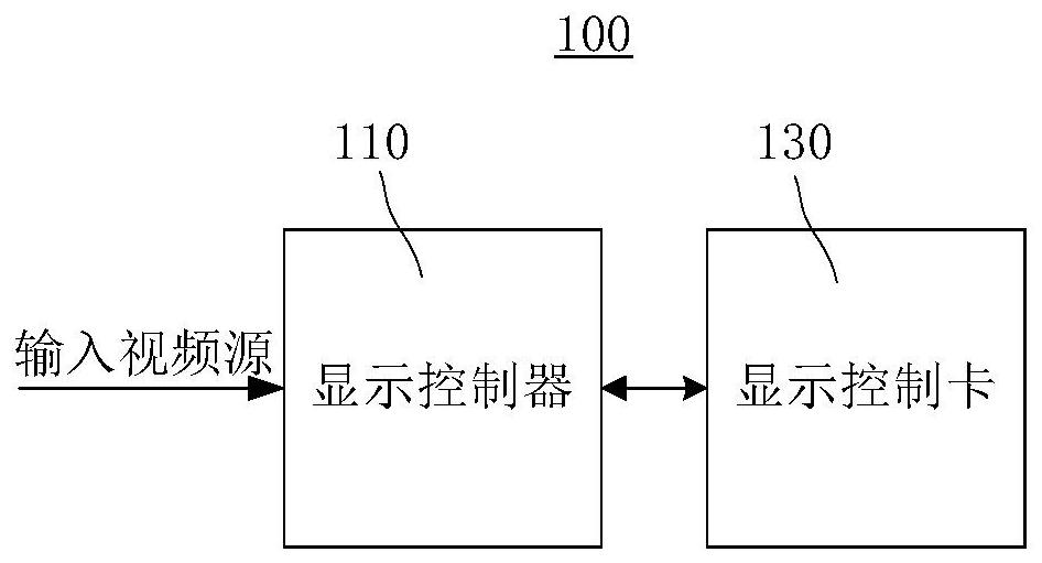
[0031] like figure 1 As shown, the first embodiment of the present invention provides a display control system 100 . Specifically, such as figure 1 As shown, the display control system 100 includes, for example: a display controller 110 and a display control card 130 connected to the display controller 110 .

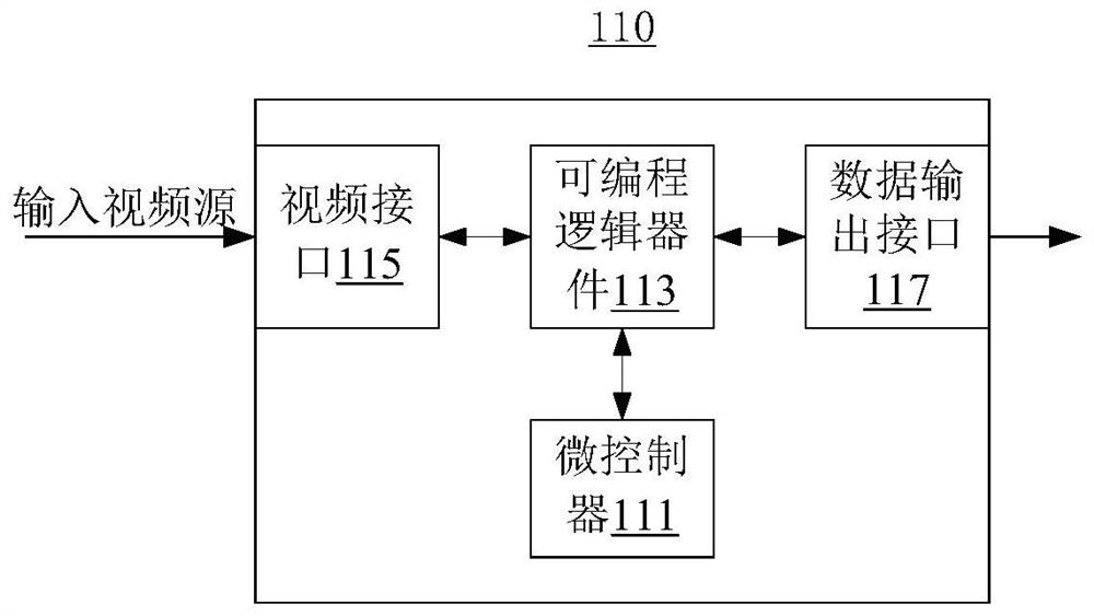
[0032] like figure 2As shown, the display controller 110 includes, for example, a microcontroller 111 , a programmable logic device 113 , a video interface 115 , and a data output interface 117 . The programmable logic device 113 is connected between the video interface 115 and the data output interface 117 . The microcontroller 111 is connected to a programmable logic device 113 . The video interface 115 is, for example, a standard video interface such as an HDMI interface, a DVI interface, and a DP interface. The data output interface 117 here includes, for example, an Ethernet physical layer transceiver, a network transformer, and a network port connected in seq...

no. 2 example

[0044] like Figure 8 As shown, the second embodiment of the present invention provides a video processing device 300 . The video processing device 300 includes, for example, a video source receiving module 310 , a video source parsing module 330 , and a data packet output module 350 .

[0045] A video source receiving module 310, configured to receive an input video source, the input video source including a first blanking period and a first effective image area located after the first blanking period and corresponding to the first blanking period , the first blanking period includes first frame rate information, and the first effective image area includes first effective image data;

[0046] A video source parsing module 330, configured to parse the input video source to obtain the first effective image data and the first frame rate information; and

[0047] The data packet output module 350 is configured to packet the first frame rate information and the first effective i...

no. 3 example

[0051] like Figure 9 As shown, the third embodiment of the present invention provides a video processing system 500 . The video source state detection system 500 includes, for example, a memory 510 and a processor 530 connected to the memory 510 . The memory 510 may be, for example, a non-volatile memory on which the computer program 511 is stored. The processor 530 may be, for example, an embedded processor. The processor 530 executes the video processing method in the foregoing first embodiment when running the computer program 511 .

[0052] For the specific working process and technical effects of the video processing system 500 in this embodiment, refer to the description of the foregoing first embodiment.


PUM


Abstract

The embodiment of the invention discloses a video processing method, device and system, a display controller, a display control system and a computer readable storage medium. The video processing method comprises the steps: receiving an input video source, wherein the input video source comprises a first blanking period and a first effective image area which is located after the first blanking period and corresponds to the first blanking period, the first blanking period comprises first frame frequency information, and the first effective image area comprises first effective image data; analyzing the input video source to obtain the first effective image data and the first frame frequency information; and packing the first frame frequency information and the first effective image data group into field packet data and outputting the field packet data. The embodiment of the invention can reduce the loss of system resources and improve the processing efficiency.

Description

technical field [0001] The present invention relates to the technical field of video processing and display, in particular to a video processing method, a video processing device, a display controller, a display control system and a computer-readable storage medium. Background technique [0002] With the rapid development of display technology, the application of display control system is becoming wider and wider. Generally, a display control system includes, for example, a display controller (or called a sending card) and a display control card (or called a receiving card). In the display control process of the input video source, the display controller usually obtains the effective image data in each frame of video by analyzing the input video source, and detects the time of the field synchronization signal of the input video source to obtain the effective image data of each frame of video. The display time of the image data further obtains the frequency (frame rate) of t...

Claims


Application Information

Patent Timeline
Patent Type & Authority Applications(China)
IPC IPC(8): H04N7/01H04N21/4402
CPCH04N7/0127H04N21/440281
Inventor 韩剑南韦桂锋
Owner XIAN NOVASTAR TECH
Learn More