
Finned tube heating surface tube structure and coal economizer

A heating tube and heating surface technology, applied in the direction of feed water heaters, preheating, tubular elements, etc., can solve the problems of fly ash wear, achieve the effects of reducing wear, reducing impact force, and increasing the temperature of the medium in the pipe

Pending Publication Date: 2021-06-18
大唐秦岭发电有限公司
View PDF0 Cites 0 Cited by
  • Summary
  • Abstract
  • Description
  • Claims
  • Application Information

AI Technical Summary

Problems solved by technology

[0004] Aiming at the problems existing in the prior art, the present invention provides a finned tube heating surface structure and an economizer. The anti-fly ash wear structure is set on the heating tube, and at the same time, heat exchange fins are arranged on the outside, which ensures that the heating tube Without reducing the heat transfer area, it solves the problem of fly ash wear on the heating surface of the low-temperature economizer working in a high-dust environment

Method used


Image

  • Finned tube heating surface tube structure and coal economizer
  • Finned tube heating surface tube structure and coal economizer
  • Finned tube heating surface tube structure and coal economizer

Examples


Embodiment Construction

[0029] The present invention will be further described in detail below in conjunction with the accompanying drawings, which are explanations rather than limitations of the present invention.

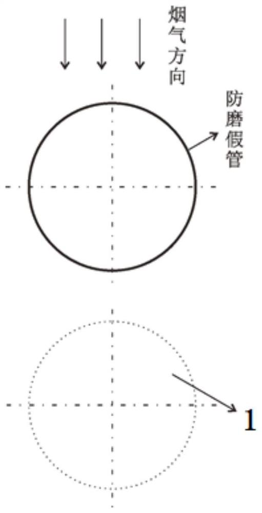
[0030] refer to Figure 2-5 , a finned tube heating surface structure, including a heating tube 1, and fins 2 and wear plates 3 connected thereto.

[0031] Multiple anti-wear plates are arranged along the circumference of the heat-receiving tube and distributed radially, the length direction of the wear-resistant plates is arranged along the axial direction of the heat-receiving tube, and multiple fins 2 are arranged in parallel, and the fins are arranged along the radial direction of the heat-receiving tube.

[0032] Multiple anti-wear plates are arranged radially in the shape of a fan, and the arc surface of the fan is facing the direction of the flue gas. Since the anti-wear plates are set at a certain slope, the fly ash particles in the boiler flue gas directly impact on the anti-wea...


PUM


Abstract

The invention discloses a finned tube heating surface tube structure and a coal economizer. The finned tube heating surface tube structure comprises a heating tube, fins and anti-abrasion plates, wherein the fins and the anti-abrasion plates are connected with the heating tube; a plurality of fins are arranged in parallel in the radial direction of the heating tube; the anti-abrasion plates penetrate through the fins and are arranged in the axial direction of the heating tube; and a plurality of anti-abrasion plates are arranged along the circumference of the heating tube and distributed in a radial shape. The anti-abrasion plates are arranged on the portion, right facing the windward side, of the heating tube, so that the problem that leakage is caused due to the fact that a finned tube on the heating surface of an existing low-temperature coal economizer is not resistant to abrasion is thoroughly solved; the anti-abrasion plates and the fins are combined on the heating tube, so that the effects of preventing leakage of the heating tube and guaranteeing the heat transfer area of the heating tube are achieved; and the anti-abrasion plates are directly welded to the heating tube, and smoke heat absorbed by the anti-abrasion plates is directly transferred to the heating surface tube, so that the area of the heating tube is increased, the temperature of media in the tube is increased, the anti-abrasion effect is achieved, the heat utilization rate is increased, and the finned tube heating surface tube structure has high use value and popularization value.

Description

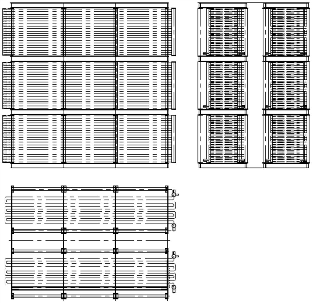
technical field [0001] The invention relates to the technical field of low-temperature economizers, in particular to a finned tube heating surface tube structure and an economizer. Background technique [0002] In order to improve the efficiency of boilers in power plants and utilize the waste heat of boiler flue gas, domestic thermal power plants generally install low-temperature economizers in the tail flue. The installation position is after the preheater and before the electrostatic precipitator equipment, which is a high-smoke arrangement. The module structure of the low-temperature economizer is arranged in front and rear groups, with a total of 60 tubes from top to bottom, and a total of 12 groups of finned tubes in front and back along the airflow direction. Each group consists of 2 tubes, a total of 24 heating tubes, and the cabinet specification is Φ38×4.5mm, see details figure 1 . [0003] The anti-wear measure of the design of the low-temperature economizer mod...

Claims


Application Information

Patent Timeline
Patent Type & Authority Applications(China)
IPC IPC(8): F28F1/32F28F19/00F22D1/10
CPCF22D1/10F28F1/325F28F19/002
Inventor 康德林
Owner 大唐秦岭发电有限公司
Learn More