
Submarine cable protection structure for single-pile composite cylinder foundation

A technology for protecting structures and tube foundations. It is applied in infrastructure engineering, cable installation, ground cable installation, etc. It can solve problems such as easy damage, power failure, and inconsistent shape, so as to avoid material waste, simple overall structure, and easy construction. The effect of assembly

Pending Publication Date: 2021-06-18
SHANGHAI INVESTIGATION DESIGN & RES INST
View PDF0 Cites 0 Cited by
  • Summary
  • Abstract
  • Description
  • Claims
  • Application Information

AI Technical Summary

Problems solved by technology

[0003] As a large channel for offshore power transmission, the protection of submarine cables is very important. Once a submarine cable fails, it will cause a large-scale power outage, affect the normal production of offshore wind farms, and cause huge economic losses.
According to the construction experience of existing offshore wind farms, the most prone to failure is the section of submarine cable extending from the seabed to the J-shaped pipe fixed on the monopile, because this section of submarine cable is in an exposed and suspended state. Very vulnerable to damage and not adequately protected
If the J-shaped tube is used to protect this section of the submarine cable, there will be problems such as inconsistent shapes and waste of materials.

Method used


Image

  • Submarine cable protection structure for single-pile composite cylinder foundation
  • Submarine cable protection structure for single-pile composite cylinder foundation

Examples


Embodiment Construction

[0029] The specific implementation manners of the present invention will be described in further detail below in conjunction with the accompanying drawings. These embodiments are only used to illustrate the present invention, not to limit the present invention.

[0030] In the description of the present invention, it should be noted that the terms "longitudinal", "transverse", "upper", "lower", "vertical", "horizontal", "top", "bottom", "inner", The orientation or positional relationship indicated by "outside" is based on the orientation or positional relationship shown in the drawings, which is only for the convenience of describing the present invention and simplifying the description, rather than indicating or implying that the referred device or element must have a specific orientation, Constructed and operative in a particular orientation and therefore are not to be construed as limitations of the invention.

[0031] In addition, in the description of the present inventi...


PUM


Abstract

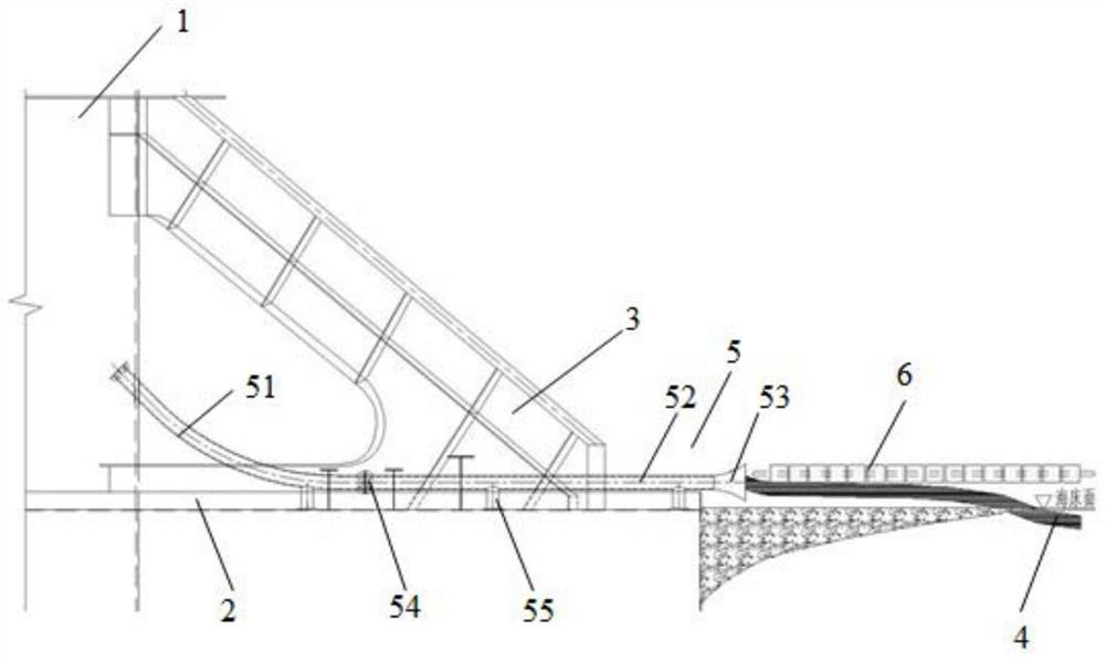
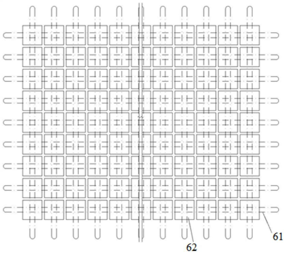
The invention provides a submarine cable protection structure for a single-pile composite cylinder foundation. The submarine cable protection structure comprises a protecting tube and a pressing and covering piece, wherein the protecting tube comprises an arc-shaped section, a straight section and a bell mouth which are sequentially communicated; the arc-shaped section is arranged at the joint of a single pile and a top cover; the straight section is arranged above the top cover; the bell mouth is located at the outer edge of the top cover; and the pressing and covering piece is pressed and covered on a submarine cable above the seabed surface and at the outer side of the bell mouth. The submarine cable protection structure has the beneficial effects that the problem that submarine cables in an existing single-pile composite cylinder foundation cannot be reasonably wired is effectively solved by arranging the protecting tube and the pressing and covering piece which are formed by connecting different sections, the phenomenon of material waste caused by adopting a traditional J-tube is avoided, and the submarine cables are protected against damage on the seabed surface any more. The whole submarine cable protection structure well adapts to the structure of the single-pile composite cylinder foundation, the submarine cable is protected by effectively utilizing the structural characteristics of the single-pile composite cylinder foundation, and the submarine cable protection structure is simple in overall structure and easy to construct and assemble.

Description

technical field [0001] The invention relates to the technical field of offshore wind turbine construction, in particular to a submarine cable protection structure for a single-pile composite barrel foundation. Background technique [0002] As the renewable energy with the most development value, wind energy has attracted worldwide attention. my country has a vast territory, long coastline, and abundant offshore wind energy resources. Due to the large area of ​​shallow overburden foundations in Liaoning, Shandong, Zhejiang, Fujian, Guangdong, Guangxi and other coastal areas in China, the bedrock surface has a shallow burial depth, and it is often impossible to sink steel pipe piles to the required design elevation, and it is necessary to install them on the rock-socketed Construction, construction period is long and difficult. The single-pile composite barrel foundation combines the traditional single-pile foundation with the barrel foundation, and the two are connected by c...

Claims


Application Information

Patent Timeline
Patent Type & Authority Applications(China)
IPC IPC(8): F03D13/20F03D13/25E02D27/12E02D27/52H02G3/04H02G9/02
CPCE02D27/12E02D27/52F03D13/22F03D13/25H02G3/0462H02G9/025Y02E10/72Y02E10/727Y02E10/728
Inventor 校建东张权王正昱王李吉蔡小莹李腾飞
Owner SHANGHAI INVESTIGATION DESIGN & RES INST
Learn More