Controlling the position of turbine guide vanes and of a coolant flow

A technology of turbines and guide vanes, applied in electrical control, engine control, machine/engine, etc., can solve problems such as carbon deposition, and achieve cost-saving and space-saving effects

Pending Publication Date: 2021-06-18
FORD GLOBAL TECH LLC
View PDF6 Cites 0 Cited by
  • Summary
  • Abstract
  • Description
  • Claims
  • Application Information

AI Technical Summary

Problems solved by technology

In addition, in this case there is a risk of carbon deposits on the diffuser area of ​​​​the compressor

Method used


Image

  • Controlling the position of turbine guide vanes and of a coolant flow
  • Controlling the position of turbine guide vanes and of a coolant flow
  • Controlling the position of turbine guide vanes and of a coolant flow

Examples


Embodiment Construction

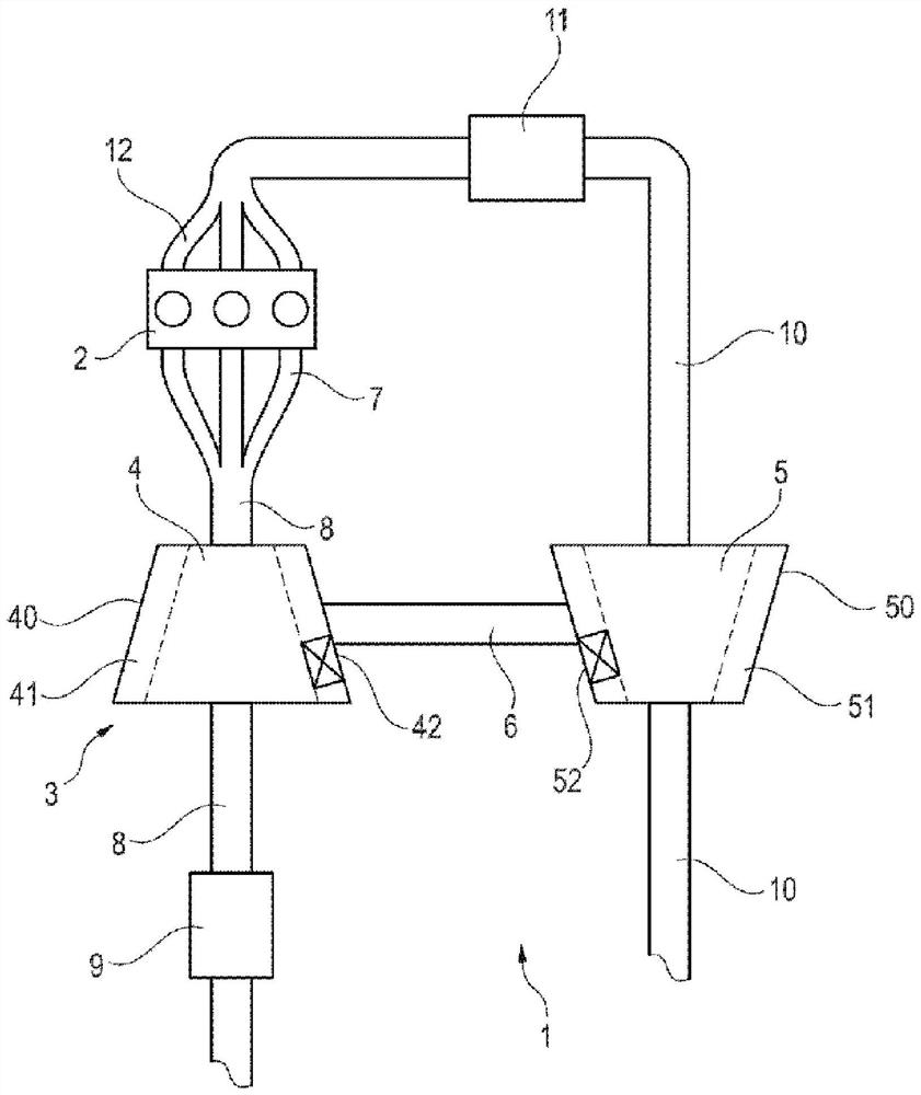
[0036] exist figure 1A component 1 for an internal combustion engine 2 with a turbocharger 3 is shown in . The turbocharger 3 has a turbine 4 and a compressor 5 , the impellers of which are connected to each other for common rotation by means of a shaft in a bearing 6 . according to figure 1 , the internal combustion engine 2 has three cylinders, but is not limited thereto. From the internal combustion engine 2 , exhaust gases are discharged from the cylinders via an exhaust line 7 , which converges via a manifold to form an exhaust duct 8 . The turbine 4 is arranged in the exhaust tract 8 downstream of the internal combustion engine 2 . The turbine wheel is driven by the exhaust gas flow produced by the internal combustion engine 2 by burning fuel. The rotation of the turbine wheel is transmitted to the compressor wheel through the shaft.

[0037] A catalytic device 9 for exhaust gas purification is arranged downstream of the turbine 4 . As catalytic devices, for exampl...


PUM


Abstract

Disclosed is controlling the position of turbine guide vanes and of a coolant flow. An assembly and a method for controlling the flow of coolant are provided, the assembly includes an exhaust turbocharger,The exhaust gas turbocharger has: a variable geometry turbine arranged in an exhaust passage of an internal combustion engine; and a compressor.The compressor is arranged in the intake passage of the internal combustion engine, the variable geometry turbine and the compressor each have a casing, a cooling jacket is integrated into at least one of casings, and the turbine has at least one guide vane,The guide vane can be rotated about its axis and the position of the guide vane can be changed by means of a first rod connected to the actuator, And the cooling jacket in the casing of the turbine or compressor has at least one valve for controlling the flow of the coolant, the valve being connected to the actuator via another rod.

Description

technical field [0001] The invention relates to an assembly of an exhaust-gas turbocharger comprising a turbine with guide vanes movable by means of an actuator, wherein the actuator also controls a valve in the cooling jacket, and to Method for controlling guide vanes and valves. Background technique [0002] Exhaust turbochargers are provided to increase the efficiency of internal combustion engines. In this case, some of the energy from the exhaust gas of the internal combustion engine is used to drive a turbine wheel, which via a shaft drives a compressor for the intake air of the internal combustion engine. An exhaust-gas turbocharger typically consists of three main components, each with a separate housing, namely a turbine, a compressor, and a shaft connecting the turbine and compressor for common rotation. [0003] In modern turbines, movable guide vanes are used to control the exhaust gas flow in the helical casing of the turbine. In this context the term variabl...

Claims


Application Information

Patent Timeline
Patent Type & Authority Applications(China)
IPC IPC(8): F02B39/00F02B29/04F02B39/16
CPCF02B39/00F02B29/0475F02B39/16F02B39/005F02B37/24Y02T10/12F02D23/00F05D2260/20F05D2220/40F02D41/0007
Inventor F·J·布林克曼L·斯塔姆普C·韦伯S·奎林K·S·库尔贝奇J·梅林
Owner FORD GLOBAL TECH LLC
Why Eureka
Try Eureka