
Active corner driving device and rotary car coupler

A driving device and turning angle technology, which is used in transportation and packaging, railway car body parts, railway vehicle coupling accessories, etc. The effect of load, simple structure

Active Publication Date: 2021-06-18
CRRC QINGDAO SIFANG ROLLING STOCK RES INST +1
View PDF8 Cites 4 Cited by
  • Summary
  • Abstract
  • Description
  • Claims
  • Application Information

AI Technical Summary

Problems solved by technology

[0003] Aiming at the technical problem that the centering device does not have the technical problem of actively controlling the rotation angle of the mechanical structure, the present invention proposes an active rotation angle driving device and a rotating coupler

Method used


Image

  • Active corner driving device and rotary car coupler
  • Active corner driving device and rotary car coupler
  • Active corner driving device and rotary car coupler

Examples


Embodiment Construction

[0053] The technical solutions in the embodiments of the present invention will be clearly and completely described below in conjunction with the drawings in the embodiments of the present invention. Apparently, the described embodiments are only some, not all, embodiments of the present invention. Based on the embodiments of the present invention, all other embodiments obtained by persons of ordinary skill in the art without making creative efforts fall within the protection scope of the present invention.

[0054] In describing the present invention, it should be understood that the terms "center", "transverse", "longitudinal", "upper", "lower", "front", "rear", "left", "right", " The orientations or positional relationships indicated by "vertical", "horizontal", "top", "bottom", "inner" and "outer" are based on the orientations or positional relationships shown in the drawings, and are only for the convenience of describing the present invention and Simplified descriptions...


PUM


Abstract

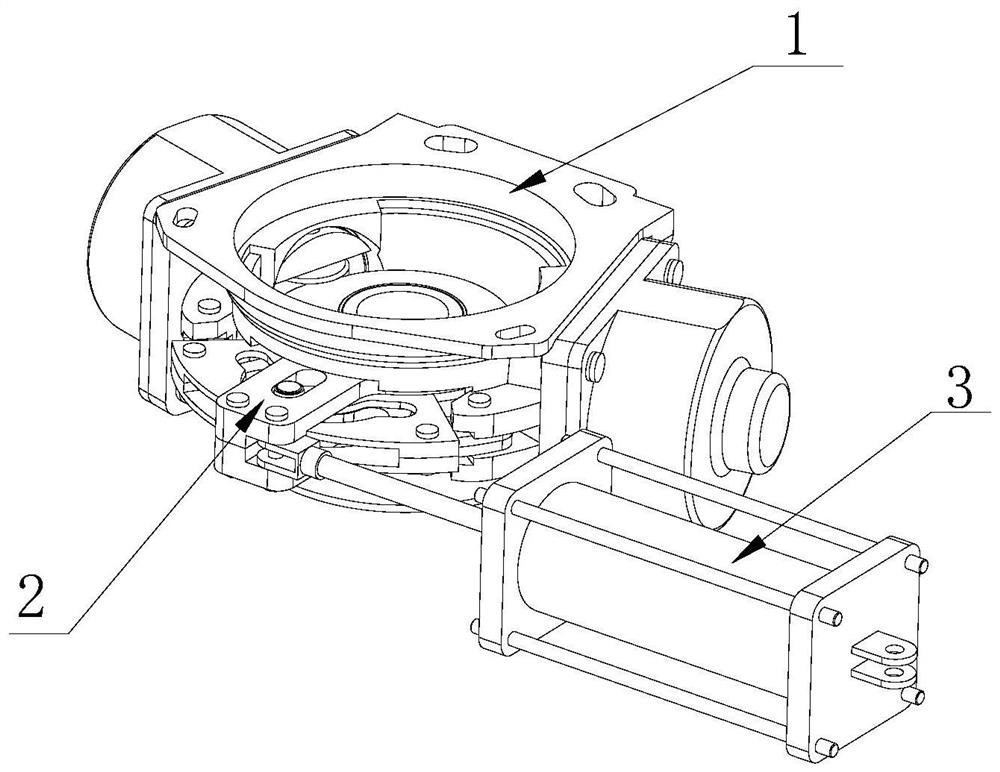
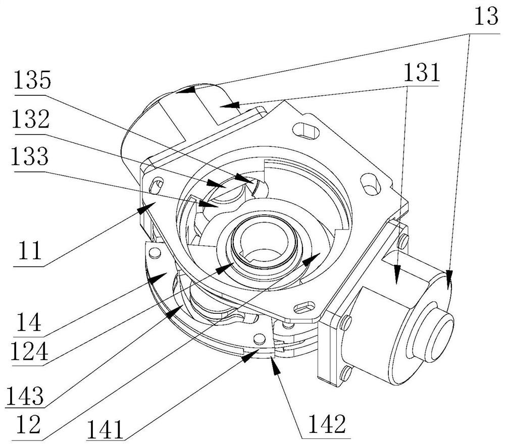
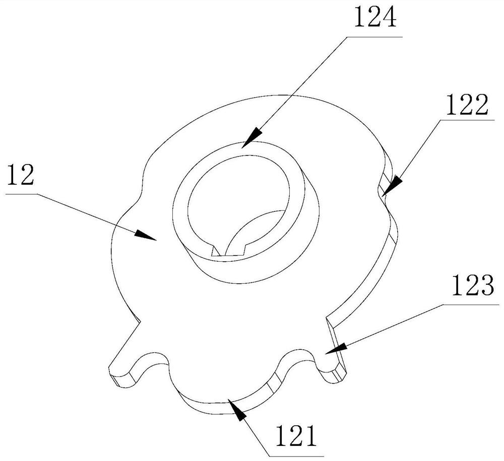
The invention provides an active corner driving device and a rotary car coupler. The device comprises a centering mechanism, the centering mechanism comprises a shell assembly, a centering disc and a piston assembly, the centering disc is arranged in the shell assembly in a pivoted mode, the piston assembly abuts against the circumferential wall of the centering disc, a sleeve, a protrusion, a notch and a cam are arranged on the centering disc, and the protrusion and the notch are symmetrically arranged on the two sides of the cam; the guide plate assembly is connected with the shell assembly and the sleeve and provided with an arc-shaped guide groove matched with the cam and the protrusion, and the protrusion is arranged in the arc-shaped guide groove; the driving mechanism is pivotally mounted in the shell assembly and comprises a cam plate assembly provided with a strip-shaped groove and a driving shaft assembly mounted in the strip-shaped groove; and the power assembly is connected with the driving mechanism. The power assembly pushes the cam plate assembly to rotate and extrude the piston assembly, the driving shaft assembly moves along the guide groove, and when the driving shaft assembly moves to make contact with the protrusion, the driving shaft assembly continues to move to push the centering disc to rotate. The centering disc is connected with a mechanical structure, and automatic rotation of the mechanical structure can be achieved.

Description

technical field [0001] The invention belongs to the technical field of rail train coupler buffer devices, and in particular relates to an active angle driving device and a rotating coupler. Background technique [0002] Generally, the couplers of trams and subway projects are equipped with centering devices that cannot be rotated automatically, and the automatic horizontal swing of the couplers cannot be realized. There is a disclosed coupler rotating mechanism in the prior art, which can realize the function of rotating the coupler at any angle in the horizontal direction. When the coupler needs to swing horizontally, the air intake of the cylinder is first cut off, and the return spring of the cylinder moves the tappet of the cylinder backward, and simultaneously drives the roller and the arc notch of the internal gear cam disc to separate, and the internal gear cam disc is in a free state. At this time, the external gear transmission mechanism is driven to rotate by a bi...

Claims


Application Information

Patent Timeline
Patent Type & Authority Applications(China)
IPC IPC(8): B61G7/06
CPCB61G7/06
Inventor 陆青松吴翠杰李朝曦任帅田倩倩朱星辰
Owner CRRC QINGDAO SIFANG ROLLING STOCK RES INST
Learn More