
Crankshaft positioning mechanism of numerical control end face milling and center hole drilling machine tool

A technology for drilling a center hole and a positioning mechanism, which is used in positioning devices, metal processing mechanical parts, clamping and other directions, can solve the problems of low positioning accuracy, low repeat positioning accuracy, and complex structure, and achieve the effect of improving positioning accuracy.

Inactive Publication Date: 2021-06-18
SHENYANG MASCH TOOL CO LTD
View PDF6 Cites 0 Cited by
  • Summary
  • Abstract
  • Description
  • Claims
  • Application Information

AI Technical Summary

Problems solved by technology

[0004] The existing crankshaft fixture usually only adopts the end shaft positioning, the positioning accuracy is low, the repeated positioning accuracy is not high, and the structure is relatively complicated, which is inconvenient to install and use.

Method used


Image

  • Crankshaft positioning mechanism of numerical control end face milling and center hole drilling machine tool
  • Crankshaft positioning mechanism of numerical control end face milling and center hole drilling machine tool
  • Crankshaft positioning mechanism of numerical control end face milling and center hole drilling machine tool

Examples


Embodiment Construction

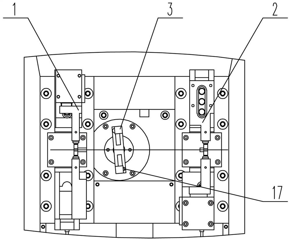
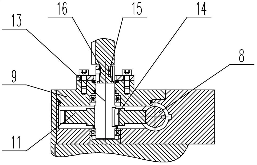
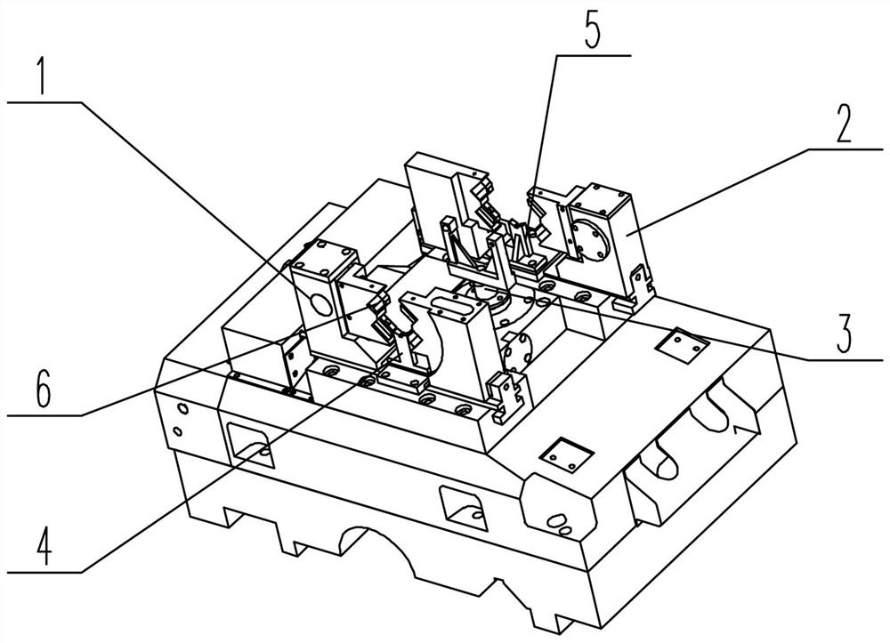
[0021] Such as figure 1 and figure 2 As shown, a crankshaft positioning mechanism of a CNC milling end face drilling center hole machine tool, the left clamping mechanism 1 and the right clamping mechanism 2 are arranged symmetrically on both sides of the base 9, and the left clamping mechanism 1 and the right clamping mechanism 2 are separated. The opening and closing end faces are provided with preload pads 6 which are in contact with the two ends of the crankshaft to be processed, and the left bracket 4 supporting the crankshaft is provided at the bottom of the opening and closing of the left clamping mechanism 1, and clamped on the right The bottom of the mechanism 2 is provided with a right bracket 5 supporting the crankshaft, and the left bracket 4 and the right bracket 5 are connected to the base 9 at the corresponding position; between the left clamping mechanism 1 and the right clamping mechanism 2, a The axial positioning pawl 3 is driven and rotated by the power u...


PUM


Abstract

The invention relates to a crankshaft positioning mechanism of a numerical control end face milling and center hole drilling machine tool. According to the crankshaft positioning mechanism, a left clamping mechanism and a right clamping mechanism are symmetrically arranged on the two sides of a base correspondingly, the left clamping mechanism and the right clamping mechanism do opening and closing movement, opening and closing end faces are provided with pre-tightening cushion blocks making contact with the two ends of a crankshaft to be machined, a left material supporting frame for supporting the crankshaft is arranged at the bottom of an opening and closing position of the left clamping mechanism, a right material supporting frame for supporting the crankshaft is arranged at the bottom of the right clamping mechanism, the left material supporting frame and the right material supporting frame are connected with the corresponding positions of the base, an axial positioning claw driven by a power device to rotate is arranged between the left clamping mechanism and the right clamping mechanism, the axial positioning claw is of a shifting fork structure, and the shifting fork structure makes contact with the surface of the crankshaft to be machined after rotating in place. The positioning mechanism is used for a clamping and positioning procedure needed in the process of machining a center hole and an end face of the crankshaft, the positioning precision is high, and the machining precision is guaranteed.

Description

technical field [0001] The invention relates to a crankshaft positioning mechanism of a CNC machine tool for milling end face and drilling a center hole, which belongs to the auxiliary tooling of the CNC machine tool. Background technique [0002] With the continuous development of the automobile industry, the processing technology of crankshaft parts has become the focus of the development of the manufacturing industry. Crankshaft workpiece fixtures are widely used in mechanical equipment. Due to the special shape of crankshaft parts, it is not easy to clamp, and the selection of fixtures directly affects the quality of workpiece processing. . [0003] The CNC milling end face drilling center hole machine tool is a CNC machine tool that mainly processes the two ends of the shaft and the center hole. It is widely used in industries such as automobiles, tractors, engines, motors, and hydraulic machines. In order to complete the above process in one clamping, and according to...

Claims


Application Information

Patent Timeline
Patent Type & Authority Applications(China)
IPC IPC(8): B23Q3/08
CPCB23Q3/08B23Q3/082
Inventor 于春明牟永凯张亮卢成斌战福操李航谭晓东霍洪旭张荣磊张宝赵伟高宇张允潘洋王保岩王萌霍明安鑫王茂宁于铎程健曲炎张洪钧张先杰汪宗泉宋锦江顾红光方恩辉刘明治张翠青
Owner SHENYANG MASCH TOOL CO LTD
Learn More