
Welding tongs of spot welding robot

A technology of robot welding tongs and welding tongs, applied in the field of artwork display, can solve problems such as cables being easily damaged and broken, and achieve the effect of preventing the reduction of service life

Pending Publication Date: 2021-06-18
ANHUI UNIVERSITY OF TECHNOLOGY AND SCIENCE
View PDF8 Cites 0 Cited by
  • Summary
  • Abstract
  • Description
  • Claims
  • Application Information

AI Technical Summary

Problems solved by technology

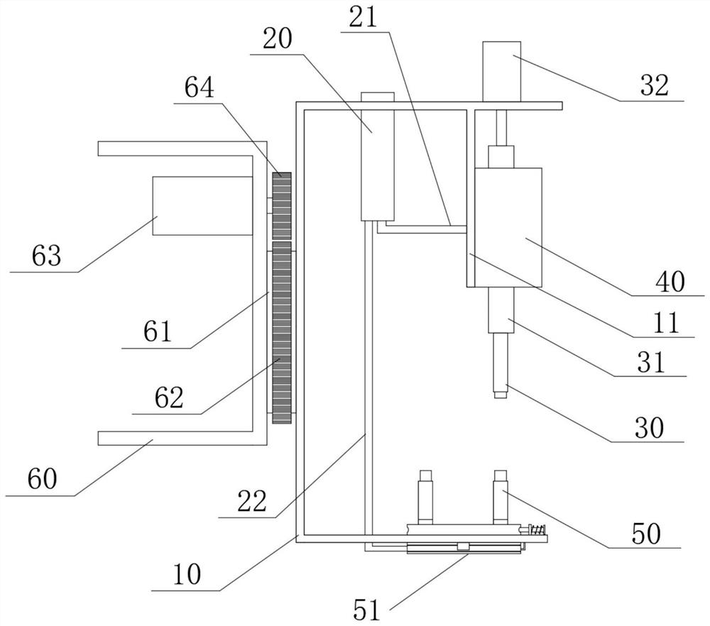
[0005] The technical problem to be solved by the present invention is to provide a welding tongs of a spot welding robot to solve the problem that the water-passing non-inductive cable on the welding tongs of the spot welding robot in the prior art described in the background technology is easily damaged and broken

Method used


Image

  • Welding tongs of spot welding robot
  • Welding tongs of spot welding robot
  • Welding tongs of spot welding robot

Examples


Embodiment 2

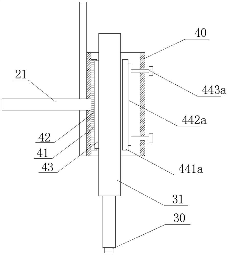
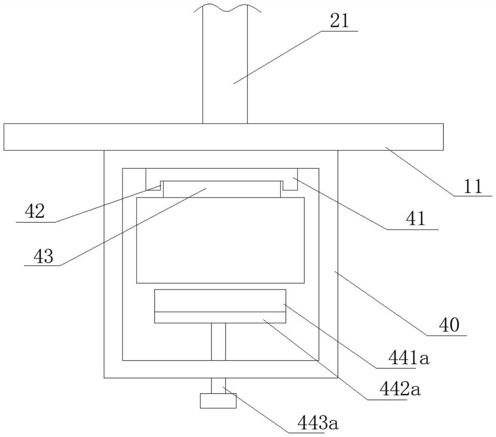
[0034] Such as Figure 2-3 The position-limiting structure 44 includes a plurality of screw rods 443a threaded on one side wall of the connecting seat 40, one end of the screw rod 443a protruding into the connecting seat 40 is connected to the rubber pad 442a in rotation, and the rubber pad 442a is provided with There is an insulating first top plate 441 a, and the conductive column 31 is between the first top plate 441 a and the conductive sliding plate 43 .

[0035] This embodiment is implemented in such a way that the provided screw 443a can drive the rubber pad 442a to move, and the rubber pad 442a can drive the first top plate 441a to move, so that the first top plate 441a squeezes the conductive column 31 into the chute 42 .

Embodiment 3

[0037] Such as Figure 4 The limiting structure 44 includes a through hole 442b disposed on one side wall of the connecting seat 40 and a U-shaped support plate 444b, the support plate 444b straddles the through hole 442b, and the through hole 442b is rotatably provided with Two rotating plates 443b. The end of the rotating plate 443b away from the through hole 442b is rotated to be provided with a second top plate 441b. The rotating plate 443b is connected to the supporting plate 444b through a first spring 445b, and the first spring 445b penetrates through the hole 442b.

[0038] This embodiment is implemented in such a way that the first spring 445b is compressed, so that the first spring 445b applies a thrust to the rotating plate 443b, so that one end of the rotating plate 443b turns into the connecting seat 40, and drives the second top plate 441b to the conductive column 31 A pushing force is applied so that the conductive column 31 is in close contact with the slide g...

Embodiment 4

[0040] Such as figure 1 , 5 The conductive seat 51 includes a conductive plate 510 that rotates through the welding tongs arm 10, and a number of insulating connecting plates 513 that are arranged on the welding tongs arm 10 and surround the conductive plate 510. The outer circumference of the conductive plate 510 An annular rotating groove 511 is arranged on the wall, and a conductive ring 512 is sleeved in the rotating groove 511. The conductive ring 512 is connected to the second cable 22, and the connecting plate 513 is fixedly connected to the conductive ring 512. The conductive disk 510 is also provided with several threaded holes 518 that run through the conductive disk 510. Several threaded holes 518 are arranged in a circular shape. Above, the threaded hole 518 is threaded with a conductive threaded column 519 , and the conductive threaded column 519 is connected to the second electrode 50 , and the welding clamp arm 10 is also provided with a blocking structure that...


PUM


Abstract

The invention discloses a pair of welding tongs of a spot welding robot, and relates to the technical field of spot welding. The pair of welding tongs of the spot welding robot comprises a welding tongs arm, wherein one side wall of the welding tongs arm is provided with a conductive seat; the other side wall of the welding tongs arm is provided with a servo air cylinder, a water-passing non-inductive cable and an insulated support arm; the conductive seat is provided with second electrodes; the support arm is provided with a connecting seat; a piston rod of the servo air cylinder is connected with a conductive column; the conductive column is connected with the connecting seat; a first electrode is arranged at the end, away from the servo air cylinder, of the conductive column; the first electrode directly faces the second electrodes; a first cable on the water-passing non-inductive cable is electrically connected with the conductive column through the connecting seat; and a second cable on the water-passing non-inductive cable is electrically connected with the second electrodes through the conductive seat. The pair of welding tongs of the spot welding robot provided by the invention has the advantages of convenience in use, high flexibility, high maintenance efficiency, long service life of the the water-passing non-inductive cable, and the like.

Description

technical field [0001] The invention relates to the technical field of artwork display, in particular to a welding tongs of a spot welding robot. Background technique [0002] Spot welding refers to the welding method that uses cylindrical electrodes to form solder joints between the contact surfaces of two overlapping workpieces during welding; during spot welding, first pressurize to make the workpieces come into close contact, and then connect the current, under the action of resistance heat The contact part of the lower workpiece melts and forms solder joints after cooling; spot welding is mainly used for welding stamping parts of thin plate members with a thickness of less than 4mm, especially suitable for welding automobile bodies, compartments, and aircraft fuselages. However, containers with sealing requirements cannot be welded. [0003] Welding tongs refer to the necessary tools for welders to hold welding rods and realize welding; the structure of welding tongs i...

Claims


Application Information

Patent Timeline
Patent Type & Authority Applications(China)
IPC IPC(8): B23K11/11B23K11/31
CPCB23K11/11B23K11/31B23K11/314
Inventor 江本赤吴婷梁利东王建彬疏达潘家保刘玉飞
Owner ANHUI UNIVERSITY OF TECHNOLOGY AND SCIENCE
Learn More