Automatic pneumatic positioning perforating machine for perforating tail part of medical suture needle

A suture needle and punching machine technology, applied in the field of punching machines, can solve the problems of high processing difficulty, high loss rate, low efficiency, etc., and achieve high punching accuracy, fast punching speed, and improve quality and production efficiency. Effect

Pending Publication Date: 2021-06-18
董松
View PDF0 Cites 0 Cited by
  • Summary
  • Abstract
  • Description
  • Claims
  • Application Information

AI Technical Summary

Problems solved by technology

The suture needles of this technology are very small. In the past, the sewing needles were processed one by one manually on a small watch lathe. The positioning process was processed first, and then the punching process was processed. The processing was difficult and the efficiency was low, and each person’s manual operation was different, resulting in punching. Inaccurate depth, size and center-to-center distance, resulting in unstable connection quality of subsequent sutures and high loss rate

Method used


Image

  • Automatic pneumatic positioning perforating machine for perforating tail part of medical suture needle
  • Automatic pneumatic positioning perforating machine for perforating tail part of medical suture needle
  • Automatic pneumatic positioning perforating machine for perforating tail part of medical suture needle

Examples


Embodiment

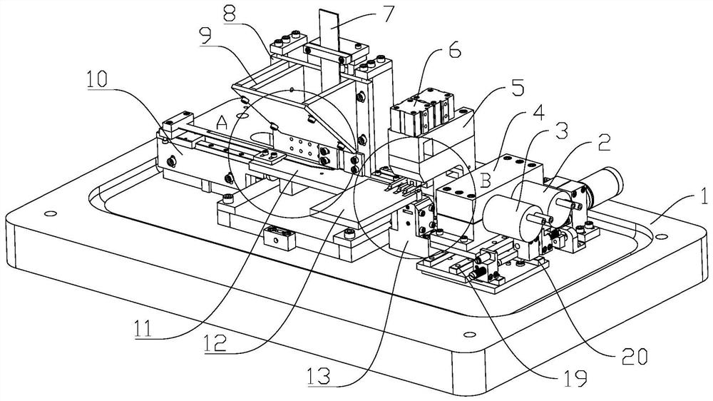
[0037] Please refer to figure 1 , figure 1 The schematic view of the embodiment of the present invention is shown in the present invention, and this embodiment provides a medical sewing needle 21 tail hole perforation, aperture, aperture, aperture, and a table 1, a fixing assembly, a positioning assembly 3, and a drilling assembly 2. The above table 1 can carry the fixing assembly, the positioning assembly 3, and the drilling assembly 2, facilitate the mounting of the components, positioning assemblies 3, and the drilling assembly 2. The fixing assembly is used to secure the suture 21 to prevent the suture 21 from sliding when drilling, resulting in a decrease in the drilling quality. The positioning assembly 3 is used to achieve the positioning of the tail opening point of the suture pin 21, and the opening position is accurate, avoiding the bias. The drilling assembly 2 described above is a direct drilling member, which is responsible for punching in the tail of the stitch 21.

...


PUM


Abstract

The invention provides an automatic pneumatic positioning perforating machine for perforating the tail part of a medical suture needle, and relates to the technical field of perforating machines. The automatic pneumatic positioning perforating machine for perforating the tail of the medical suture needle comprises a workbench, a fixing assembly, a positioning assembly and a drilling assembly, wherein the workbench can bear the fixing assembly, the positioning assembly and the drilling assembly, so that installation of the fixing assembly, the positioning assembly and the drilling assembly is facilitated. The fixing assembly is used for fixing the suture needle, so that the situation that the suture needle slides during drilling, and consequently the drilling quality is reduced is prevented. The positioning assembly is used for positioning a tapping point at the tail of the suture needle, so that the tapping position is accurate, and the problem of hole deviation is avoided. The drilling assembly is a direct drilling part and is responsible for drilling at the tail part of the suture needle. According to automatic pneumatic positioning perforating machine disclosed by the invention, automatic perforating of the tail part of the medical suture needle can be achieved, the perforating precision is high, the perforating speed is high, and the quality and production efficiency of the medical suture needle are greatly improved.

Description

Technical field [0001] The present invention relates to the field of punching machines, and in particular, therefore, in particular, a medical suture tail tail hole is automatically pneumatically positioning a punch. Background technique [0002] The traditional drilling method is the manual operation watch trunk, according to the stitching of the stitching needle, a suitable chuck is installed, and the sewing needle is processed on the caching, the depth of processing is observed by the naked eye. To the specified depth stop, the fine suture can not be completed, because the stitching needle is too small to take it, it is difficult to operate, and it is difficult to operate, so artificially punched small needles cannot process only the sewing of imports. needle. Medical suturing needle punching is the third generation of products that are currently developing in the needle industry, which requires the current state-of-the-art punch technology, drilling in the tail and the needle...

Claims


Application Information

Patent Timeline
Patent Type & Authority Applications(China)
IPC IPC(8): B23B41/00B23B47/20B23Q7/00B23Q7/10B23Q3/08
CPCB23B41/00B23Q3/062B23Q3/082B23Q5/36B23Q7/00B23Q7/10
Inventor 董松
Owner 董松
Why Eureka
Try Eureka