
Quick-preheating air sterilization equipment

A technology of air sterilization and equipment, applied in the direction of deodorization, disinfection, separation methods, etc., can solve the problems of humidity, bacteria contamination equipment, easy to grow bacteria, etc., to avoid the effect of sputtering

Active Publication Date: 2021-06-18
怀蕊(广州)科技有限公司
View PDF15 Cites 0 Cited by
  • Summary
  • Abstract
  • Description
  • Claims
  • Application Information

AI Technical Summary

Problems solved by technology

[0003] Based on the inventor's discovery above, the existing air degerming equipment with fast preheating mainly has the following deficiencies, for example: when the microorganisms in the air are killed at high temperature, the moisture mixed in the air is subjected to high temperature Evaporation will also occur due to the impact. The moisture evaporates and attaches to the inside of the equipment, making the inside of the equipment in a humid state for a long time, and it is easy to grow bacteria, causing bacteria to contaminate the equipment.

Method used


Image

  • Quick-preheating air sterilization equipment
  • Quick-preheating air sterilization equipment
  • Quick-preheating air sterilization equipment

Examples


Embodiment 1

[0028] Example 1: Please refer to Figure 1-Figure 6 , the specific embodiments of the present invention are as follows:

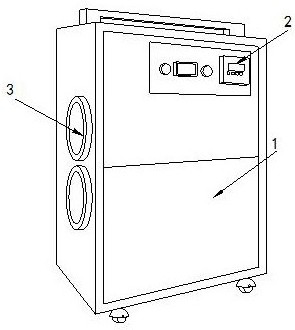
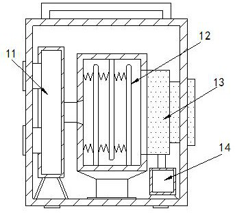
[0029] Its structure includes a main body 1, a control panel 2, and an air inlet 3. The front end of the main body 1 is provided with a control panel 2, and two air inlets 3 are provided, and are respectively installed on the side faces of the main body 1. The main body 1 It includes a wind storage chamber 11, a sterilization block 12, a water removal device 13, and a water storage tank 14. The wind storage chamber 11 is arranged on the left side of the main body 1, and the sterilization block 12 is located in the middle of the main body 1. The water device 13 is connected to the right side of the sterilization block 12, and the water storage tank 14 is installed at the bottom of the water removal device 13.

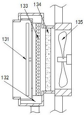
[0030] Described water removal device 13 comprises water attachment device 131, water storage tank 132, activated carbon plate 133, air purificatio...

Embodiment 2

[0035] Example 2: Please refer to Figure 7-Figure 9 , the specific embodiments of the present invention are as follows:

[0036] The water channel a4 includes an outer water rejection groove c1, a water rejection block c2, and a rubber ring c3. The bottom end of the outer rejection groove c1 is embedded with a water rejection block c2, and the inside of the water rejection block c2 is hollow, so One end of the rubber ring c3 is connected to the bottom end of the outer throwing tank c1, and the other end is connected to the side end of the water throwing block c2. The end surface of the rubber ring c3 is curved, which is beneficial to concentrate the water flow through the rubber ring c3 , to carry out the pilot flow in the water throwing block c2.

[0037] The water rejection block c2 includes a water rejection tank c21, a water drop hole c22, a water collecting ring c23, and a concentration block c24. The water removal tank c21 is arranged in the middle of the water rejecti...


PUM


Abstract

Quick-preheating air sterilization equipment is disclosed. The equipment structurally comprises a main body, a control panel and two air inlets, wherein the control panel is arranged at the front end of the main body; the two air inlets are formed in the side end faces of the main body respectively; the main body comprises an air storage cavity, a sterilization block, a water removal device and a water storage tank; the water removal device comprises a water adsorption device, a water storage tank, an activated carbon plate, an air purification plate and a fan; the water adsorption device comprises a water adsorption plate, a clamping shaft, a water guide device, a water passing groove and a through hole; the water guide device comprises a water guide block, a water guide groove and a water collection block; the water collection block comprises a sliding groove, a sliding block, a contact block and a rubber band. Water in air is in contact with the end face of the water adsorption device to be condensed into small water drops, then airflow is used for impacting the end face of the water adsorption device, and therefore the water adsorption device is driven to rotate, the water is thrown out, loss of the water adsorbed in the water adsorption device is accelerated, the water adsorption device is prevented from being in a humid state for a long time, and the condition that bacteria grow in the main body is avoided.

Description

technical field [0001] The invention relates to the field of air medium filtration and sterilization, in particular to air sterilization equipment with fast preheating. Background technique [0002] Air microbial pollution is one of the causes of respiratory infection, but regarding the seriousness of air microbial pollution and how to effectively remove air microbial pollution, air pollution is still a big problem nowadays. Through the method of high temperature sterilization, the microorganisms placed in the air can be completely killed. [0003] Based on the inventor's discovery above, the existing air degerming equipment with fast preheating mainly has the following deficiencies, for example: when the microorganisms in the air are killed at high temperature, the moisture mixed in the air is subjected to high temperature Evaporation will also occur in the impact, and the water evaporates and attaches to the inside of the equipment, making the inside of the equipment in a...

Claims


Application Information

Patent Timeline
IPC IPC(8): B01D53/26A61L9/16
CPCB01D53/265B01D53/261A61L9/16
Inventor 王琼
Owner 怀蕊(广州)科技有限公司
Learn More