
Bidirectional isolation type DC/DC converter

A two-way isolation and converter technology, which is applied to the conversion equipment with intermediate conversion to AC, DC power input to DC power output, instruments, etc. It can solve the problem of high control difficulty, large loss, uncontrollable gain and power size, etc. problem, to achieve the effect of consistent gain and efficiency, and smooth switching

Active Publication Date: 2021-06-15
BEIJING JIAOTONG UNIV
View PDF6 Cites 0 Cited by
  • Summary
  • Abstract
  • Description
  • Claims
  • Application Information

AI Technical Summary

Problems solved by technology

However, in order to ensure the same gain in both directions, the parameters of the resonant network need to be calculated and verified complexly, and when the power direction changes, the control strategy of the switching devices on both sides also needs to be changed, making the control difficult
For the cascade solution of non-isolated DC / DC converters and LLC resonant converters, the LLC resonant converter operating at the resonant frequency can achieve efficient power transmission when the power flows in both directions, but its gain and power cannot be controlled , so a non-isolated DC / DC converter is required to control the gain and power
However, cascaded non-isolated DC / DC converters also pass all the power at the same time, and most of them cannot achieve soft switching, resulting in large losses
[0004] Therefore, there is an urgent need for a bidirectional isolated DC / DC converter to overcome the difficulties of single-stage LLC resonant converters in applications where power flows bidirectionally and the problems of complex control and large losses in existing bidirectional power topologies.

Method used


Image

  • Bidirectional isolation type DC/DC converter
  • Bidirectional isolation type DC/DC converter
  • Bidirectional isolation type DC/DC converter

Examples


Embodiment

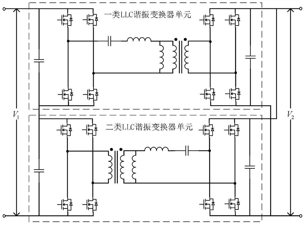
[0031] figure 1 For the connection topology diagram of a bidirectional isolated DC / DC converter provided in this embodiment, refer to figure 1 , the bidirectional isolated DC / DC converter includes: two LLC resonant converter units.

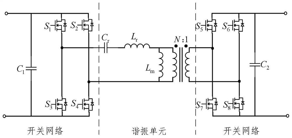
[0032] figure 2 It is a schematic structural diagram of the LLC resonant converter unit of this embodiment, referring to figure 2, the LLC resonant converter unit includes two switching networks and a resonant unit, the resonant unit includes a resonant capacitor Cr, a resonant inductance Lr and a transformer with a turn ratio of N, and the excitation inductance of the transformer is Lm.

[0033] from figure 1 It can be seen that the switch network in this embodiment is a full bridge circuit, wherein the switches S1 and S3, and S2 and S4 are respectively connected in series to form two bridge arms, and the two bridge arms are connected in parallel with the DC side capacitor C1 to form a full bridge circuit. Similarly, S5, S6, S7, S8, and C2 ...


PUM


Abstract

The invention provides a bidirectional isolation type DC / DC converter and a control method thereof. The bidirectional isolation type DC / DC converter comprises at least two LLC resonant converter units; each LLC resonant converter unit comprises two switching networks and a resonant unit; each resonant unit comprises a resonant capacitor, a resonant inductor and a transformer, a first interface of the first switching network is connected in series with the resonant capacitor, the resonant inductor and one winding of the transformer and then is connected to a second interface of the first switching network, and two ends of the other winding of the transformer are respectively connected with two interfaces of the second switching network; and all the LLC resonant converter units are divided into two types, the first switching networks of all the first-class LLC resonant converter units are connected in series with the second networks of all the second-class LLC resonant converter units, and the second switching networks of all the first-class LLC resonant converter units are connected in parallel with the first networks of all the second-class LLC resonant converter units. Bidirectional gain and efficiency consistency and smooth power commutation can be realized.

Description

technical field [0001] The invention relates to the technical field of DC / DC converters, in particular to a bidirectional isolation DC / DC converter. Background technique [0002] The size of passive components in an isolated DC / DC converter can be greatly reduced as the switching frequency continues to increase, but its switching loss will increase significantly. As a typical topology of the isolated DC / DC converter, the LLC resonant converter with unidirectional power flow can realize the zero-voltage switching of the primary switching tube of the transformer and the zero-current switching of the secondary switching tube in the full load range, thus Reduce switching loss, improve conversion efficiency, and reduce electromagnetic interference. Due to the above advantages, the LLC resonant converter is widely used in the occasion of unidirectional power flow to achieve higher power density. At the same time, the LLC resonant converter has different resonance characteristics...

Claims


Application Information

Patent Timeline
Patent Type & Authority Applications(China)
IPC IPC(8): H02M3/335H02M3/28
CPCH02M3/33584H02M3/285Y02B70/10
Inventor 吴学智牛靖凯荆龙童亦斌
Owner BEIJING JIAOTONG UNIV
Learn More