
Power control equipment for low voltage

A technology for power control and equipment, applied in electrical components, substation/distribution device enclosures, substation/switch layout details, etc. Heat dissipation and other problems, to achieve the effect of simple and convenient installation and removal of the filter, quick installation and removal, and easy maintenance

Inactive Publication Date: 2021-06-15
安徽永汇新材料科技有限公司
View PDF0 Cites 0 Cited by
  • Summary
  • Abstract
  • Description
  • Claims
  • Application Information

AI Technical Summary

Problems solved by technology

[0002] Power control equipment refers to the control equipment that is composed of several power components to realize the control of one or some objects, so as to ensure the safe and reliable operation of the controlled equipment, although the existing power control equipment can realize the control of power components However, when there are power components to work, a large amount of heat will be generated, too much heat can not be dissipated quickly, and the existing heat dissipation method generally has a heat dissipation port or a heat dissipation fan on the outer wall of the box to dissipate heat, but this This method leads to easy accumulation of dust inside the box, and the components of the power components are more precise. Too much dust will affect the working efficiency of the power components, or cause the problem of unstable working efficiency of the power components

Method used


Image

  • Power control equipment for low voltage
  • Power control equipment for low voltage
  • Power control equipment for low voltage

Examples


Embodiment 1

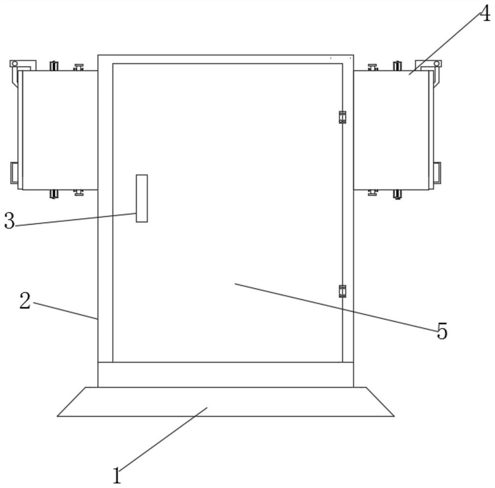
[0025] A kind of electric control equipment for low voltage, comprising a control box 2, the lower end of the control box 2 is provided with a base 1, in order to facilitate the opening or closing of the control box 2, the surface of the control box 2 is hinged with a box door 5, the box A door handle 3 is fixed on the door 5; a cooling mechanism 4 is arranged on both sides of the control box 2;

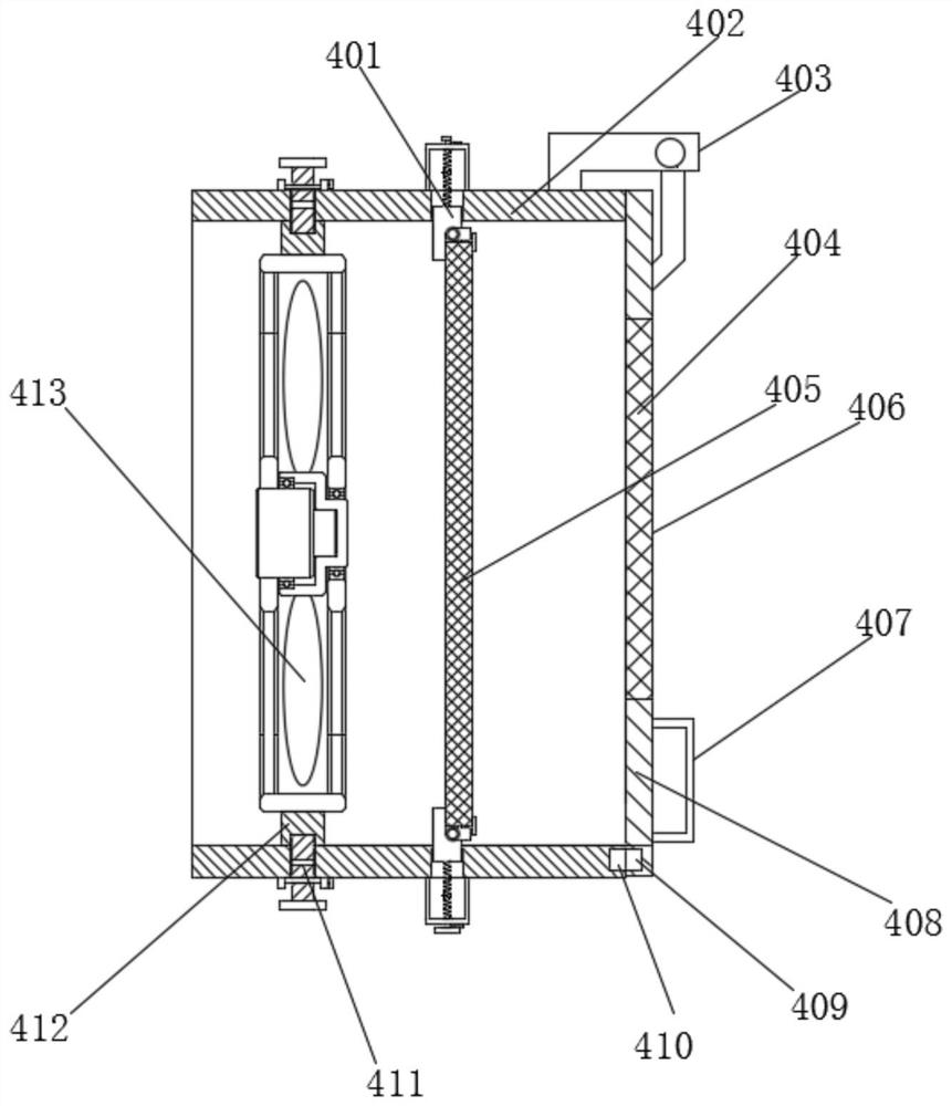
[0026] The heat dissipation mechanism 4 includes a housing 402 fixed on the outer wall of the control box 2, the housing 402 communicates with the inside of the control box 2, the inside of the housing 402 is provided with a filter 405, and both sides of the filter 405 are provided with an adjustment mechanism 401 The side of the filter 405 adjacent to the control box 2 is provided with a fan 413. In order to discharge heat faster, the fan 413 in the housing 402 is a blowing type, and the fan 413 in the housing 402 on the other side is an exhausting type. The upper and lower ends of ...

Embodiment 2

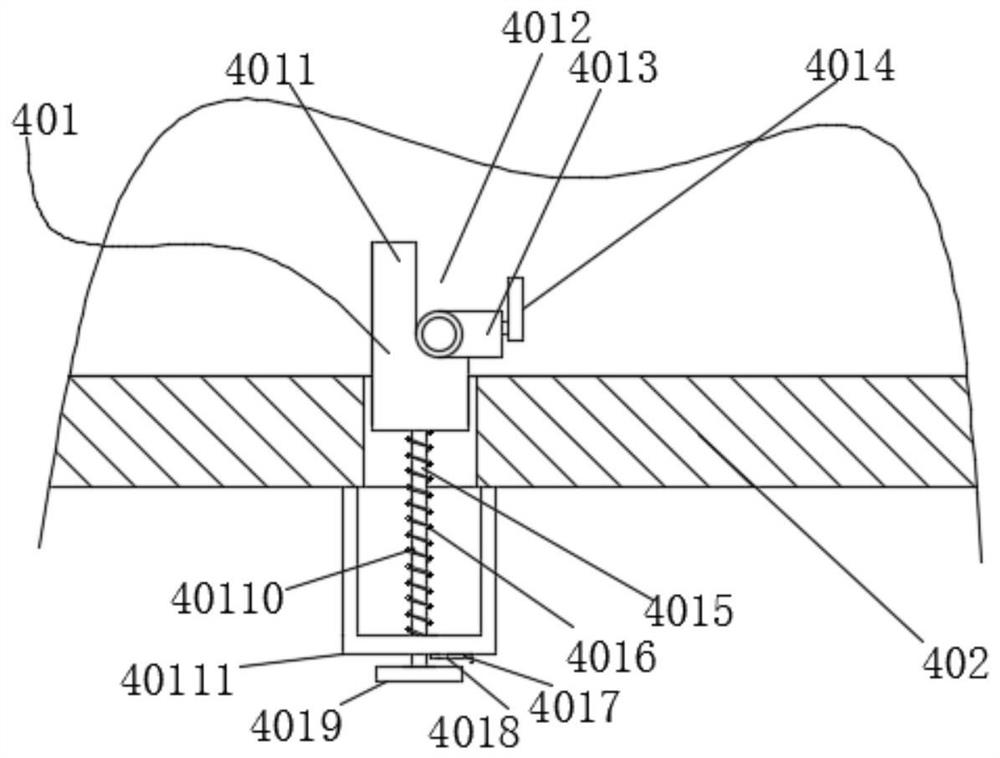
[0029] As an option, see Figure 1-4 , a kind of electric power control equipment for low voltage, the adjustment mechanism 401 includes a fixed bracket 40111 fixed on the outer wall of the housing 402, the middle of the fixed bracket 40111 is provided with a through support 4015, the outside of the support 4015 is sleeved with a spring 4016, the support The upper end of 4015 is provided with a movable plate 4011, and the lower end of the pillar 4015 penetrates the fixed bracket 40111 and is provided with a first pull block 4019, the movable plate 4011 penetrates the outer wall of the housing 402 and extends into the interior of the housing 402, and the right side of the movable plate 4011 is provided with a notch 4012, the bottom of the notch 4012 is provided with a hinged rotating baffle 4013, the outer side of the rotating baffle 4013 is provided with a rotating block 4014, the filter screen 405 is fixed in the notch 4012, one end of the spring 4016 is connected on the fixed...


PUM


Abstract

The invention discloses power control equipment for low voltage, and belongs to the technical field of power control equipment. The power control equipment comprises a control box body, wherein the lower end of the control box body is provided with a base, and the two sides of the control box body are provided with heat dissipation mechanisms; the heat dissipation mechanism comprises a shell fixed to the outer wall of the control box body, the shell is communicated with the interior of the control box body, a filter screen is arranged in the shell, and adjusting mechanisms are arranged on the two sides of the filter screen.According to the invention, heat dissipation is carried out through the heat dissipation mechanisms, air is blown to the control box body through a fan of the shell on one side, air is exhausted from the interior of the control box body through a fan of the shell on the other side so as to take away heat, the heat dissipation efficiency is improved, air enters the interior of the control box body from the shell, dust is prevented through the filter screen, the dust is prevented from infecting power elements of the control box body and affecting the working efficiency of the power elements, and the problem of unstable working efficiency of the power component is avoided.

Description

technical field [0001] The invention belongs to the technical field of power control equipment, and in particular relates to a low-voltage power control device. Background technique [0002] Power control equipment refers to the control equipment that is composed of several power components to realize the control of one or some objects, so as to ensure the safe and reliable operation of the controlled equipment, although the existing power control equipment can realize the control of power components However, when there are power components to work, a large amount of heat will be generated, too much heat can not be dissipated quickly, and the existing heat dissipation method generally has a heat dissipation port or a heat dissipation fan on the outer wall of the box to dissipate heat, but this This method leads to easy accumulation of dust inside the box, and the components of the power components are relatively precise. Too much dust will affect the working efficiency of th...

Claims


Application Information

Patent Timeline
Patent Type & Authority Applications(China)
IPC IPC(8): H02B1/56H02B1/28H02B1/48
CPCH02B1/28H02B1/48H02B1/56
Inventor 许来王守鹏金燕李凯时霞锋李学光张婷
Owner 安徽永汇新材料科技有限公司
Learn More